Cavitation damage begins when vapor cavities form in a low-pressure region and collapse near a ceramic surface, producing localized impacts, pits, grain removal, and progressive chipping. Abrasion requires solid particles to slide, roll, or strike the surface, more often leaving directional grooves, polished tracks, rounded flow edges, or distributed wall loss. Before changing the ceramic grade, engineers should evaluate damage location, surface morphology, slurry data, pump operating point, and response to operating changes together.
A harder material cannot correct vapor-cavity generation, while more suction head cannot eliminate particles trapped in a clearance. Decide first whether correction belongs in the pump system, the component specification, or both.
What Does Cavitation Damage Look Like on Ceramic Pump Parts?
Cavitation starts when local pressure falls below vapor pressure. Cavities form, enter a higher-pressure region, and collapse. Near a solid boundary, microjets and pressure pulses repeatedly load small areas. In a centrifugal pump, relevant locations include the impeller eye, suction-side blades, recirculation zones, and restrictions.
Bubble Formation, Transport, and Near-Wall Collapse
On a ceramic impeller, wear sleeve, seal ring, or flow-passage insert, cavitation erosion may appear as isolated pits, clustered craters, grain pull-out, or porous-looking roughness. As damage develops, adjacent pits can merge and leave irregular material loss. An edge exposed to the collapse field may progressively chip because the remaining ceramic section carries increasingly concentrated stress.
Location is as important as appearance. A cluster of pits in a hydraulically credible collapse zone is stronger evidence than similar roughness spread uniformly over every wetted surface. The inspection should preserve the component’s orientation relative to the impeller eye, pump casing, cutwater, and direction of rotation.
Supporting evidence includes noise or vibration that changes with flow or suction condition; head deterioration; restricted suction, low tank level, or elevated liquid temperature; off-design operation with recirculation; and damage where hydraulic analysis predicts cavity collapse.
These observations support a hypothesis; none proves cavitation. Particle impact, porosity, corrosion, and machining defects can also resemble pitting.
Why NPSH3 Is Not a Zero-Damage Threshold
The Hydraulic Institute defines NPSH3 as the available net positive suction head at which first-stage pump head has fallen by 3% because of cavitation. It is a performance criterion—not the first vapor cavity or a guarantee of zero erosion. Projects need an application-specific margin based on pump guidance, liquid, speed, operating range, and reliability target. See the Hydraulic Institute definitions and pump FAQ.
Cavitation Signatures in Brittle Ceramics
Repeated localized loading can activate surface flaws, machining damage, pores, weak grain boundaries, or tensile stress at a sharp edge. Resistance therefore depends on density, flaw population, grain-boundary integrity, fracture toughness, surface condition, and geometry—not hardness alone.
ASTM G32-16(2021)e1 provides a controlled vibratory method for comparing cavitation-erosion behavior. ASTM warns that surface preparation affects the result and that rankings can change between test methods or field conditions. The method is useful comparative evidence, but its mass-loss curve should not be converted directly into pump service life.
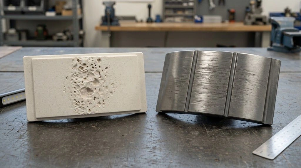
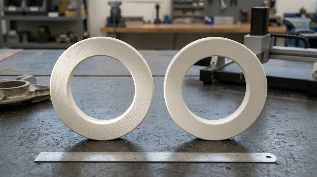
Physical ceramic pump components with localized cavitation-like pitting on one part and directional abrasive tracks on another.
How Does Abrasion Damage Differ in Slurry Service?
Abrasion requires load-bearing contact between a solid particle and the component surface. Particles may slide or roll through a close clearance, producing scratches, polishing, flattened tracks, and gradual clearance growth. In an open flow passage, particles can strike at velocity; that mechanism is more accurately called solid-particle erosion, even though plant reports often group it under “abrasive wear.”
Sliding and Rolling Abrasion in Clearances
A ceramic wear sleeve, seal ring, or bearing surface can trap particles between opposing surfaces. Relative motion pulls them along the contact path, producing parallel grooves, a polished area, a step at the track boundary, or measurable clearance increase.
Record particle-size distribution, shape, hardness, density, and solids concentration, together with counterface, clearance, load, speed, flushing, and finish. Oversized particles may control damage in a narrow gap even when the average size appears acceptable.
Particle-Impact Erosion at Edges and Bends
Where slurry changes direction, particles can leave the liquid streamline and strike impeller leading edges, bends, restrictions, cutwaters, casing inserts, or recirculation zones. Evidence includes rounded edges, directional scars, or localized thinning along the particle trajectory.
Impact angle matters: high-angle impact can initiate cracks and release fragments, while shallow impact favors scratching. Velocity, concentration, particle shape, and flow field interact, so one “abrasion resistance” number cannot represent every slurry-pump duty.
Why Hardness Alone Does Not Predict Slurry-Wear Life
Hardness helps resist indentation and scratching, but it does not describe crack propagation, grain pull-out, impact response, or corrosion-assisted weakening. Porosity, grain boundaries, toughness, machining damage, and edge geometry can change the result. Silicon carbide may suit many abrasive, chemically aggressive flow paths, while alumina, zirconia, or silicon nitride may deserve review under different cost, toughness, load, and manufacturing constraints. These are screening directions, not universal rankings.
ASTM G75-24 separates the relative abrasivity of a slurry, expressed through the Miller Number, from a material’s slurry abrasion response under that test, expressed through the SAR Number. This distinction is useful: slurry severity and material response are related but not interchangeable.
Likewise, ASTM G65-16(2021) uses a standardized dry-sand/rubber-wheel condition to rank scratching abrasion, but explicitly does not reproduce all particle, impact, pressure, or corrosive conditions in service. Test data are most useful when the mechanism, specimen preparation, particles, liquid, temperature, exposure, and reporting metric are documented.
How Can You Distinguish Cavitation, Abrasion, Corrosion, and Mechanical Chipping?
A reliable first-pass diagnosis combines four evidence groups: damage location, surface morphology, correlation with operating changes, and material or assembly context. A photograph of a detached fragment cannot provide all four. Preserve the failed part’s orientation and compare it with pump geometry and operating history before assigning a cause.
Failure-Mode Classification
| Failure mode | Root mechanism | Typical signature | Stronger supporting evidence | First corrective direction |
|---|---|---|---|---|
| Cavitation erosion | Vapor cavities collapse near the surface | Clustered pits, craters, grain pull-out, porous-looking roughness | Credible collapse zone; response to suction, temperature, speed, flow, or recirculation | Correct hydraulic cause, then review grade, surface, radii, and geometry |
| Sliding abrasion | Particles slide or roll in a loaded interface | Directional scratches, polished tracks, clearance growth | Damage follows relative motion or a particle-trapping path | Review particles, clearance, finish, counterface, and flushing |
| Solid-particle erosion | Entrained particles strike at velocity | Leading-edge loss, directional scars, rounded flow features | Damage follows a particle trajectory or high-incidence region | Review velocity, impact angle, flow geometry, solids, and microstructure |
| Corrosion-assisted wear | Chemistry weakens the surface or grain boundaries before removal | Recession, deposits, undercut grains, chemistry-dependent roughening | Rate changes with composition, concentration, temperature, or cleaning | Verify chemical compatibility and corrosion–wear interaction |
| Mechanical chipping | Assembly load, impact, misalignment, or edge stress starts brittle fracture | Corner chip, radial crack, contact imprint, fracture at a fit or clamp | Origin lies at a mounting or handling location rather than the flow field | Review edge radius, preload, support, alignment, and thermal mismatch |
| Mixed-mode damage | Two or more mechanisms accelerate loss | Pits plus grooves, recession plus pull-out, chips inside a worn zone | More than one independent operating correlation | Treat as a system problem and verify with representative testing |
Seven-Step Diagnostic Sequence
- Preserve and label the component’s position, rotation direction, and wetted orientation.
- Map damage against low-pressure regions, pressure recovery, clearances, recirculation, and particle paths.
- Photograph the whole part and repeat close-ups with scale, consistent lighting, and location IDs.
- Classify pits, grooves, polishing, edge rounding, recession, cracks, chips, and deposits separately.
- Compare the damage rate with suction pressure, liquid temperature, speed, flow, valve position, particle loading, particle distribution, chemistry, and maintenance events.
- Record a provisional primary mechanism, a secondary mechanism, and plausible alternatives rather than forcing one label.
- Choose an operating change, microscopy check, dimensional trend, chemical review, or laboratory comparison capable of falsifying the leading hypothesis.
Mixed damage is common. Cavitation may expose fresh material, particle impact may extend a pit, and corrosion may weaken grain boundaries before removal. A peer-reviewed review of centrifugal-pump deterioration treats slurry erosion and cavitation as interacting mechanisms, so one surface may record several stages.
Inspect the metal–ceramic interface: preload, poor support, interference, misalignment, or thermal-expansion mismatch can start a crack later rounded by flow and misclassified as erosion.
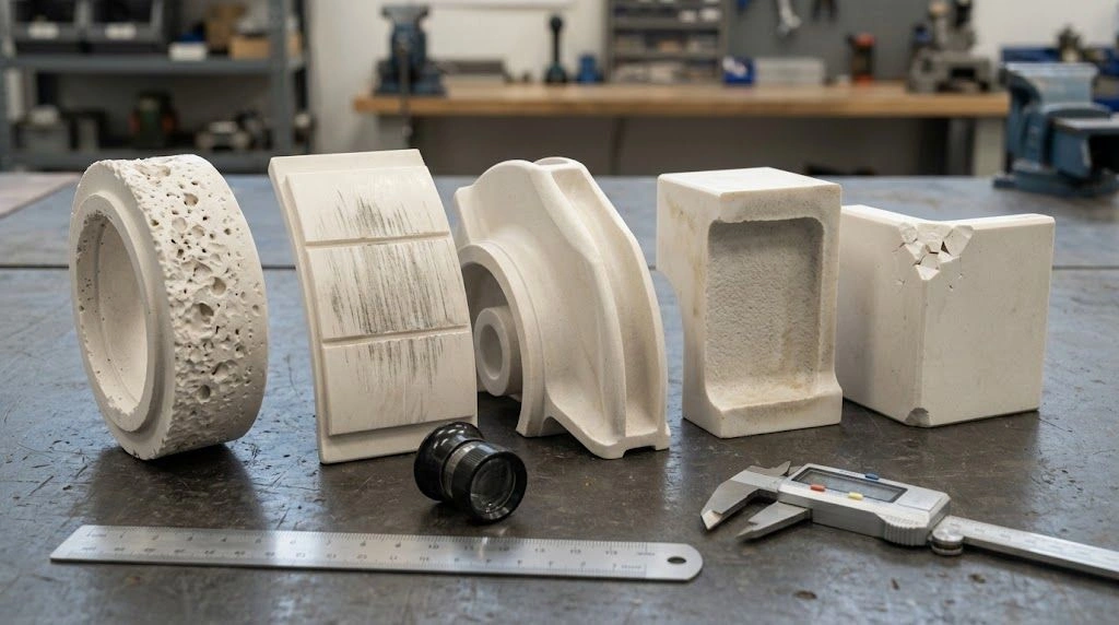
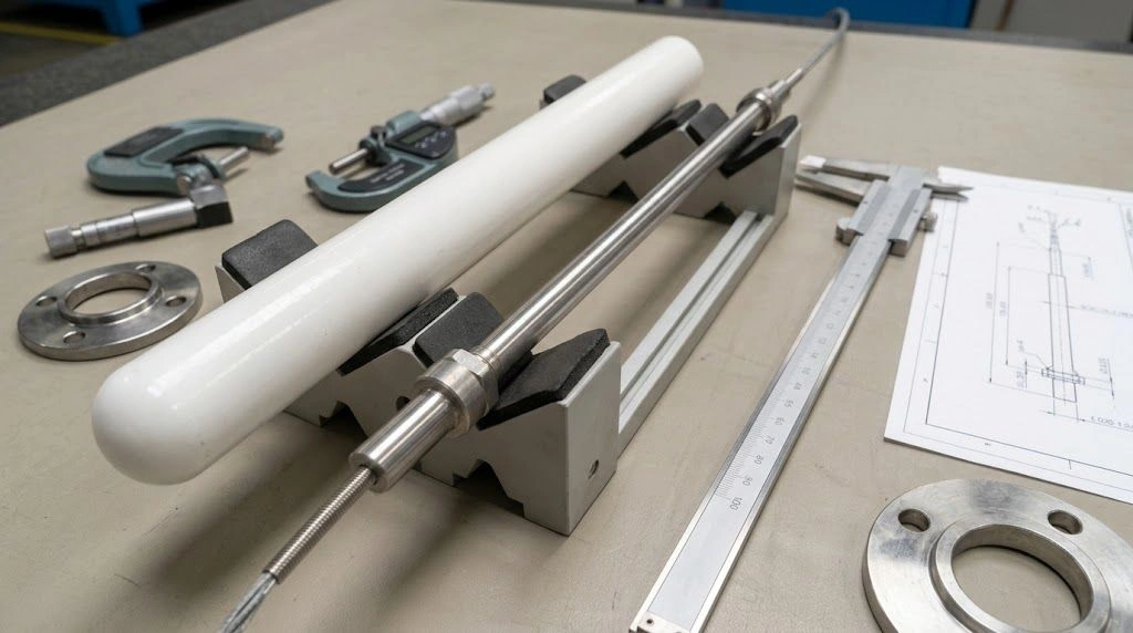
An inspection-bench comparison of pitting, directional grooves, rounded flow edges, surface recession, and mounting-related chips on ceramic pump parts.
Which Ceramic and Design Variables Control Damage Resistance?
Material selection should follow the dominant loading mechanism, not a generic ranking. Define what loads the surface, where cracks can start, how chemistry affects the grade, and whether manufacturing or mounting will add flaws.
Selection Threshold Matrix
| Observed evidence | Dominant variable to investigate | Selection or design direction | Evidence required before release |
|---|---|---|---|
| Localized pits in a plausible collapse zone; noise or vibration changes with suction | NPSH margin, inlet loss, vapor pressure, speed, operating region | Correct hydraulic condition first; then review cavitation-resistant grade, finish, and edge design | Pump curve, NPSHA basis, liquid temperature, operating point, damage map |
| Directional grooves or polished tracks in a clearance | Particle hardness, size, shape, clearance, contact, flushing | Review dense hard ceramic, clearance, flush strategy, counterface, and finish together | Particle distribution, mating material, clearance, finish requirement |
| Leading-edge or bend loss follows particle trajectory | Velocity, impact angle, solids loading, local geometry | Review erosion-resistant grade and flow-path geometry as one system | Flow, solids concentration, particle data, orientation |
| Recession with deposits or grain-boundary attack | Chemistry, temperature, corrosion–wear interaction | Confirm chemical compatibility and grade composition before wear ranking | Medium, concentration, pH, temperature, cleaning cycle |
| Chips or cracks start near mounting features | Preload, alignment, impact, edge radius, thermal mismatch | Review tougher grade, radii, support, fit, and assembly controls | Drawing, mating materials, preload method, thermal cycle |
| Several patterns occur on one part | Cavitation–abrasion–corrosion synergy | Treat as combined system damage; avoid relying on one coupon ranking | Full duty cycle, photos, hydraulic history, slurry and chemistry data |
For cavitation, reduce cavity generation or move collapse away from the part first. Review suction loss, temperature, speed, operating point, inlet geometry, recirculation, and the pump manufacturer’s NPSH-margin guidance. A resistant ceramic does not remove the hydraulic source.
For close-clearance abrasion, review particle exclusion, flushing, gap, counterface, alignment, and finish. For impact erosion, check whether bends, area changes, or exposed edges concentrate trajectories. Geometry changes may outperform a grade change alone.
Specify more than a ceramic family: include grade, forming and sintering route, density or open porosity, machining and surface controls, edge break, wall thickness, and critical interfaces. Avoid sharp internal corners, abrupt sections, unsupported edges, rigid metal point contact, and tolerances that force damaging assembly loads.
Match verification to the mechanism. ASTM G32 supports cavitation comparisons; ASTM G75 supports slurry abrasivity and material-response comparisons. Coupon results do not automatically represent particle impact, corrosion synergy, component stress, or the pump flow field. Request complete test conditions and treat small ranking differences cautiously.
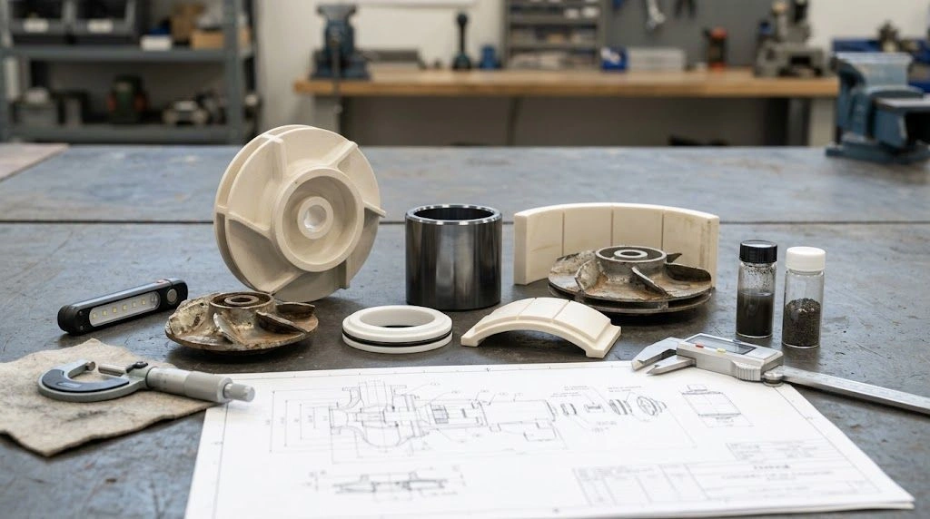
Ceramic impeller, sleeves, seal rings, and a failed reference part arranged for dimensional, surface, and application review.
What Should Be Included in a Ceramic Pump-Part RFQ?
A reviewable RFQ defines the component, assembly, fluid, particles, hydraulic duty, observed damage, and acceptance method. Sending only “silicon carbide pump part” or a photograph without scale leaves the supplier unable to distinguish material selection from hydraulic, geometric, or assembly problems.
Part and Assembly Definition
Provide the drawing or CAD model. Identify wetted surfaces, interfaces, orientation, critical dimensions, clearances, tolerances, edge radii, finish, datums, and inspection points. State mating materials and how the ceramic is supported or retained, including preload and thermal cycle where relevant.
If no drawing exists, send the old part, scaled photographs, and the dimensions to reconstruct. Separate original geometry from damage; copying a worn edge or enlarged bore can reproduce the failure.
Hydraulic, Slurry, and Chemistry Data
State liquid chemistry, concentration, pH, temperature, pressure, flow, speed, duty, cleaning, and off-design operation. For suspected cavitation, include the pump curve, actual operating point, suction arrangement, tank level, NPSHA basis, vapor-pressure input, and damage position.
For slurry service, include solids concentration, particle-size distribution, shape, hardness, density, and chemistry. Note feed changes, settling, agglomeration, or debris, and provide dated noise, vibration, head, and efficiency trends.
Failure Evidence and Acceptance Requirements
Attach overview and close-up photographs with orientation and damage zones. Add dimensional history, service hours, deposits, and the previous material record when available. Time in service is context, not a transferable lifetime guarantee.
Ask the supplier to state:
- Proposed ceramic grade and relevant manufacturing route.
- Machining, surface-finish, edge, and cleaning controls.
- Critical dimension and visual-inspection plan.
- Any material-property or wear-test method used for comparison.
- Specimen preparation, medium, particles, apparatus, temperature, exposure, and result metric for cited tests.
- Known limitations and any need for a trial installation or service-representative validation.
For an engineering review of drawings, samples, damage evidence, and duty conditions, submit the package with your inquiry for custom ceramic parts.
Copyable RFQ Checklist
- Part name, pump model context, drawing/CAD file, revision, and units.
- Old sample or photographs with scale, orientation, and exact damage location.
- Critical dimensions, clearances, tolerances, surface finish, and edge requirements.
- Current material and any available grade or inspection records.
- Liquid chemistry, concentration, pH, temperature, and pressure.
- Flow, speed, operating point, suction arrangement, NPSHA basis, and duty cycle.
- Solids concentration plus particle size, shape, hardness, density, and chemistry.
- Noise, vibration, head, efficiency, and maintenance changes.
- Mating materials, support, preload, alignment, joining method, and thermal cycle.
- Required material, dimensional, visual, and comparison-test documentation.
- Trial quantity, annual quantity, destination, packaging, and documentation needs.
Frequently Asked Questions
Can cavitation occur when NPSHA is above NPSHR?
Yes. NPSHR is commonly tied to NPSH3, not the first cavity or zero erosion. Required margin remains application-specific.
Does pitting prove cavitation?
No. Particle impact, corrosion, porosity, machining defects, and grain pull-out can look similar. Check location, history, particles, chemistry, and cracks.
Is silicon carbide always best for abrasive pump service?
No. Grade, porosity, impact, chemistry, geometry, assembly load, manufacturing, and inspection requirements can change the selection.
Which test compares cavitation-resistant ceramics?
ASTM G32 provides comparative evidence when the report identifies specimen preparation and test conditions. It is not a direct pump-life prediction.