Define the component by construction, pressure responsibility, operating exposure, and mounting before selecting a temperature-sensor protection route.
A thermowell and a protection tube both isolate a temperature sensor from its surroundings, but the names do not always describe the same construction or design responsibility. In common process-instrumentation usage, a thermowell is a mechanically engineered, process-connected well intended to withstand pressure, flow, and vibration while allowing sensor removal. A protection tube is more often a fabricated metal or ceramic sheath selected for temperature, atmosphere, corrosion, contamination, or molten-material exposure. Because terminology varies, specify the construction, connection, service loads, and governing standard rather than relying on the name alone.
What Are a Thermowell and a Protection Tube?
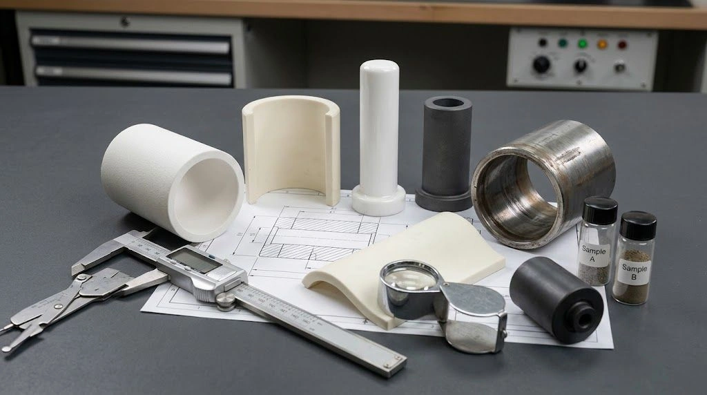
Both components place a physical barrier between a temperature sensor and the process or furnace environment. The practical distinction often comes from how the body is made, how it connects to equipment, and which mechanical or environmental responsibilities it carries. Some instrumentation suppliers reserve “thermowell” for a one-piece body machined from solid bar stock and “protection tube” for a fabricated tube with a separately closed tip. Furnace suppliers also use protection tube for a ceramic sheath around a thermocouple. These conventions overlap, so the drawing remains the controlling definition.
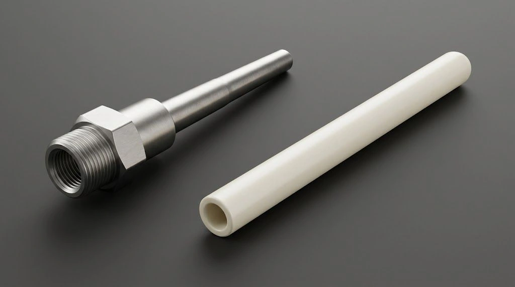
The metal thermowell and closed-end ceramic tube show different construction routes; appearance alone does not establish pressure rating or service suitability.
Common Function: Isolating the Sensor
A closed-end protective body separates a thermocouple, RTD, thermometer stem, or other sensing element from direct process contact. This barrier can reduce chemical attack, contamination, abrasion, or mechanical exposure. It can also allow the sensing insert to be removed while the external protective body remains installed.
That shared function does not make all protective bodies equivalent. A component penetrating a pressurized pipeline may form part of the containment boundary. A ceramic tube passing through a furnace wall may primarily shield the sensor from hot gas, flame, deposits, or electrical contact. These duties create different design evidence and failure risks.
Construction-Based Industry Definitions
WIKA describes a common industrial distinction: a thermowell is made from one piece of solid bar stock, while a fabricated protection tube is constructed from tubing closed by a welded solid tip. Ashcroft’s threaded thermowell provides a product-level example of one-piece bar-stock construction for pressurized, high-velocity, or corrosive media.
Ceramic protection tubes follow another construction route. They may be formed as closed-end tubes or used within assemblies that combine a ceramic sheath, sensor, insulation, connection head, and metal mounting hardware. Ceramics are not welded into an equivalent one-piece metallic pressure component, so their interfaces, brittle behavior, thermal expansion, and support need separate review.
Why the Drawing Controls the Definition
Supplier and regional terminology is not perfectly consistent. A fabricated metal tube may be called a thermowell, and some protection tubes are engineered for process loads. The name should therefore lead to six checks:
- Body construction and material.
- Open- or closed-end geometry.
- Process and instrument connections.
- Pressure-boundary responsibility.
- Flow, thermal, chemical, and mechanical loads.
- Applicable standard, calculation, and acceptance evidence.
| Question | Thermowell | Protection tube |
|---|---|---|
| Common construction usage | Frequently a solid-machined metal body with an integral closed end | Frequently a fabricated metal tube with a closed tip or a formed ceramic tube |
| Pressure role | Common in pressurized piping and vessels, subject to design verification | May or may not retain pressure; ceramic furnace tubes should not be assumed pressure-rated |
| Flow loading | Often a primary design concern | Application-dependent; relevant in flowing gas, reactor, or immersion service |
| Common environments | Process piping, vessels, chemical systems, power equipment | Furnaces, kilns, reactors, incinerators, and molten-material measurement |
| Main risks | Pressure, corrosion, bending, vibration, fatigue, connection failure | Thermal shock, chemical attack, contamination, erosion, brittle fracture, mounting constraint |
| Main specification error | Selecting by alloy and insertion length alone | Selecting by nominal temperature capability alone |
When Should You Use a Thermowell or a Protection Tube?
Choose the route from the operating duty. A pressure-service thermowell is the usual starting point when a sensor penetrates a pressurized pipe or vessel and must be removed without opening the process. A ceramic protection tube is more relevant when furnace temperature, atmosphere, flame, deposits, electrical insulation, contamination, abrasion, or molten-material contact dominates. Fabricated metallic protection tubes occupy an intermediate area when their construction and ratings match the actual process loads.
Pressure Piping and Process Vessels
For a pressurized flowing process, establish pressure, temperature, medium, velocity, density, connection, unsupported length, and operating transients. The review may need to address static pressure, corrosion allowance, bending, fatigue, and flow-induced vibration. Sensor removal during operation is useful only when the installed well and process connection continue to contain the medium safely.
ASME PTC 19.3 TW-2016 has a defined scope for specified thermowell constructions and installations. Its presence in a project specification does not automatically qualify every welded tube, ceramic sheath, coating, sleeve, or custom geometry. The engineer must compare the actual construction and installation against the current standard and project code.
Furnaces, Kilns, and High-Temperature Atmospheres
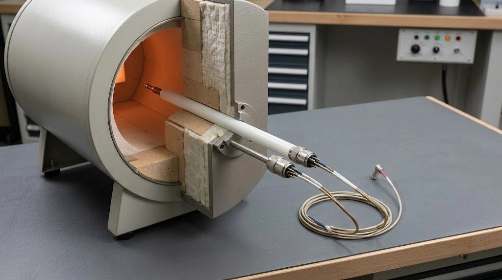
In a furnace or kiln, the protection problem may be heat, atmosphere chemistry, flame impingement, deposits, electrical insulation, or sensor contamination rather than pipeline pressure. A ceramic tube can place a chemically and thermally suitable barrier around the sensor while extending into the heated zone.
Mounting remains a mechanical design task. A long ceramic tube needs alignment, appropriate support, clearance through wall penetrations, and allowance for differential thermal expansion. A nominal material temperature does not establish survival under a specific ramp rate, thermal gradient, atmosphere, or rigid clamp.
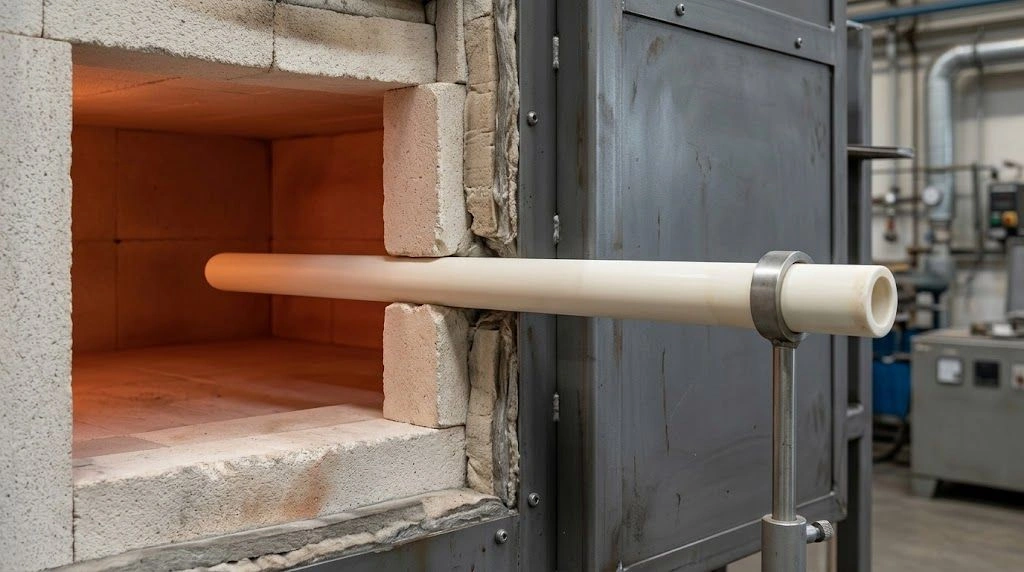
The installation illustrates a furnace protection route with external support; it is a generic application scene without customer or performance claims.
When a Multi-Layer Assembly May Be Required
High pressure and severe high-temperature chemistry can occur together. One material or tube may not efficiently perform every function. An engineered assembly can assign pressure retention to a qualified metallic component and chemical or thermal protection to another layer, provided sealing, sensor clearance, heat transfer, and differential expansion are addressed.
Define which component contains pressure, which protects against the environment, and which centers or insulates the sensor. Each interface adds thermal resistance and possible constraint, so the complete assembly requires review.
| Application condition | Starting route | Required confirmation |
|---|---|---|
| Pressurized liquid or gas pipeline | Engineered thermowell | Pressure design, medium, velocity, geometry, vibration, connection, and code |
| Pressurized reactor vessel | Thermowell or reviewed multi-layer assembly | Pressure-boundary ownership, corrosion, gradients, and nozzle design |
| Atmospheric furnace or kiln | Ceramic or metallic protection tube | Atmosphere, peak and transient temperatures, deposits, mounting, and sensor type |
| Flame or particulate exposure | Application-specific protection tube | Impingement, erosion, thermal gradient, wall design, and response |
| Non-ferrous molten material | Chemistry-compatible protection tube | Melt composition, wetting, immersion, cycling, and cleaning practice |
| Hot corrosive gas under pressure | Engineered multi-layer solution may be needed | Pressure layer, chemical layer, sealing, and expansion |
| Fast control response | Low-mass reviewed design | Strength, thermal shock, sensor fit, response criterion, and protection trade-off |
Why Does the Name Alone Not Prove Suitability?
Calling a part a thermowell does not establish its pressure rating, fatigue margin, corrosion compatibility, or behavior at a particular flow velocity. Calling another part a protection tube does not make it a low-risk accessory. A long ceramic tube can crack because of thermal gradients, impact, misalignment, rigid mounting, or differential expansion. Suitability comes from matching the physical construction to the load case and installation.
A Thermowell Name Is Not a Rating
A catalogue name cannot replace a material certificate, drawing, connection rating, calculation, fabrication record, or applicable code review. Unsupported length and stem geometry affect mechanical behavior in flowing media. A custom connection or coating may also place the part outside the scope of a standard method used for another construction.
When a thermowell vibrates or fails, “the alloy was too weak” is not a defensible conclusion without examining flow conditions, geometry, natural frequency, mounting, corrosion, and the relevant calculation scope.
Temperature Capability Is Not Thermal-Shock Evidence
Ceramic material tables often contain maximum-use temperatures under particular assumptions. Those figures do not define the allowable heating rate, insertion practice, thermal gradient, support contact, atmosphere, or accumulated degradation for a finished tube.
A crack near a ceramic tube mount may involve rigid constraint, point contact, misalignment, differential expansion, or a transient gradient. The observed location guides investigation but does not establish the root cause. Process history and physical evidence are required.
Protection Changes Sensor Response
A thermowell or protection tube introduces wall thickness, thermal mass, sensor clearance, and additional interfaces. Deposits can add another layer. Increasing the wall or closed-end thickness may improve mechanical protection or erosion allowance while slowing response and increasing thermal gradients.
A slow reading does not automatically identify a defective thermocouple. Review immersion, sensor-to-bore clearance, tip contact, deposits, wall geometry, material conductivity, flow, and the response requirement for the complete assembly.
| Observation | Weak conclusion | Better review direction |
|---|---|---|
| Thermowell vibrates or fails | The alloy was too weak | Check velocity, density, unsupported length, geometry, frequency, mounting, and calculation scope |
| Ceramic tube cracks near the mount | Its temperature capability was too low | Check constraint, alignment, edge contact, expansion, and transient gradient |
| Sensor responds slowly | The thermocouple is defective | Review wall, air gap, tip contact, deposits, insertion, and assembly mass |
| Reading drifts over time | The transmitter must be replaced | Check contamination, atmosphere ingress, insulation leakage, deposits, and calibration evidence |
| Tube surface erodes | A thicker tube will solve it | Review particle impingement, chemistry, material, support, and response penalty |
A correct product name starts the engineering review; it does not prove pressure integrity, vibration resistance, thermal-shock survival, or measurement performance.
How Do Material, Construction, and Installation Affect Selection?
Review the sensor, protective body, and mounting as one thermal-mechanical assembly. Metallic thermowells require attention to pressure, corrosion, flow loading, connection integrity, and the applicable design method. Ceramic protection tubes shift emphasis toward atmosphere chemistry, thermal gradients, electrical behavior, contamination, molten-material compatibility, and brittle fracture at supports or edges. Geometry controls both protection and response.
Ceramic Protection-Tube Material Routes
Alumina is commonly evaluated where high-temperature electrical insulation and contamination control matter. Silicon carbide can provide higher thermal conductivity and useful wear behavior, but electrical conductivity, oxidation behavior, gas tightness, and performance depend on the grade and manufacturing route. Silicon nitride or Sialon may be considered for thermal cycling, mechanical robustness, or selected non-ferrous-melt duties after chemistry review.
Zirconia can be considered where thermal insulation, fracture resistance, or particular chemical conditions are relevant, while mullite and porcelain remain established routes for some moderate furnace duties. No family name defines a universal maximum temperature, atmosphere compatibility, thermal-shock limit, or service life.
For furnace, kiln, reactor-atmosphere, or molten-material applications, review available ceramic thermocouple protection tubes against the actual temperature profile, chemistry, geometry, electrical requirements, and mounting arrangement.
| Material route | Consider when | Advantages to evaluate | Boundaries to confirm |
|---|---|---|---|
| Alumina | Insulation, furnace atmosphere, and contamination control matter | Chemical stability in many environments and high-purity routes | Thermal gradients, purity, porosity, atmosphere, and geometry |
| Silicon carbide | Thermal transfer, abrasion, or faster transients matter | Higher conductivity and useful wear properties in suitable grades | Electrical behavior, oxidation, grade chemistry, and gas tightness |
| Silicon nitride or Sialon | Cycling, mechanical robustness, or selected melt duty dominates | Thermal-shock route and application-specific melt behavior | Grade, atmosphere, temperature, and melt chemistry |
| Zirconia | Thermal insulation or particular chemical compatibility matters | Low thermal conductivity and comparatively high fracture resistance | Response, grade selection, cost, and cycling |
| Mullite or porcelain | Moderate furnace duty and cost sensitivity | Established refractory protection route | Silica content, contamination, permeability, and duty limits |
Wall, Clearance, and Closed-End Geometry
Wall thickness and closed-end thickness trade thermal response against mechanical protection, erosion allowance, and robustness. A smaller sensor-to-bore clearance may improve heat transfer in some arrangements, but insufficient clearance can cause binding during expansion and complicate sensor replacement.
Longer insertion can reach a more representative measurement zone, yet it can increase unsupported length, bending, vibration, or breakage risk. The required immersion and support positions should be decided with the equipment geometry and sensor response needs.
Support and Differential Expansion
Ceramic-to-metal mounts need enough guidance to control movement without creating hard point loads or preventing thermal expansion. Avoid forcing a long brittle tube through misaligned openings. The flange, collar, compression fitting, or custom mount should locate the assembly while accounting for hot and cold clearances.
Support design can be as important as the ceramic grade. A stronger material cannot compensate for a sharp metal edge pressing into the tube, an unsupported span exposed to movement, or a clamp that locks incompatible thermal expansions together.
What Should a Thermowell or Protection-Tube RFQ Include?
A useful RFQ identifies the component’s responsibility before listing dimensions. State whether the item retains process pressure, shields a sensor inside a furnace, contacts molten material, or forms one layer of an assembly. Provide the sensor, temperature profile, pressure, medium, atmosphere, flow, immersion, mounting, and connection. The drawing should define the tube and interface geometry. For ceramic parts, add cycling, support, expansion, and electrical requirements.
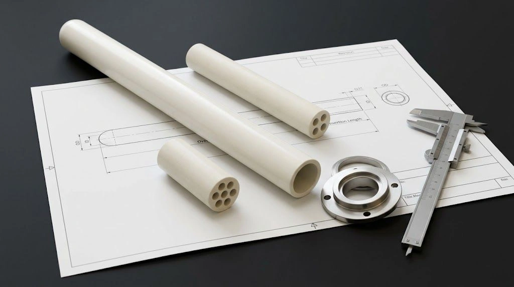
Tube geometry, closed-end details, mounting hardware, and operating conditions should be reviewed together before quotation.
Copyable Drawing Note
Provide a temperature-sensor protection component to the attached drawing. Supplier shall confirm whether the proposed item is a pressure-retaining thermowell, a non-pressure protection tube, or one layer of a multi-component assembly. Material grade, construction method, closed-end geometry, process connection, dimensional inspection, and documentation shall be stated in the quotation. Service suitability shall be reviewed against the supplied pressure, temperature profile, medium or atmosphere, flow conditions, mounting arrangement, and applicable project standard. No pressure rating, wake-frequency compliance, or maximum-use temperature shall be inferred from the product name alone.
RFQ Checklist
- Requested classification: thermowell, protection tube, ceramic sheath, or multi-layer assembly.
- Pressure-boundary responsibility and applicable project code.
- Sensor type and thermocouple arrangement where applicable.
- Continuous, peak, and transient temperature profile.
- Pressure and vacuum conditions.
- Fluid, gas, furnace atmosphere, vapor, deposit, slag, or melt composition.
- Flow velocity, density, and operating range where applicable.
- Ramp rate, cycling frequency, and shutdown conditions.
- Vertical, horizontal, or inclined mounting orientation.
- OD, ID, overall length, insertion length, and unsupported length.
- Support positions and furnace-wall penetration details.
- Closed- or open-end configuration, tip profile, and end thickness.
- Bore count and sensor clearance.
- Flange, thread, collar, compression fitting, or custom mounting interface.
- Ceramic-to-metal clearance and thermal-expansion allowance.
- Required tolerances, straightness, and interface surface condition.
- Pressure, vibration, mechanical, or response calculation requirement.
- Material, dimensional, and other required documentation.
- Quantity, project stage, drawing revision, and replacement-part evidence.
- Required acceptance or application-validation plan.
A material certificate identifies agreed material information; it does not by itself prove finished-part pressure performance, thermal-shock survival, response time, or suitability for a particular assembly. Ask the supplier to identify assumptions and any responsibility that remains with the system designer.
Send ADCERAX the controlled drawing, old-part information where available, material preference, quantities, temperature profile, atmosphere or melt chemistry, mounting arrangement, and required inspection documents at info@adcerax.com. State explicitly whether another component retains pressure so the ceramic protection-tube review begins from the correct boundary.
FAQ
Is a protection tube the same as a thermowell?
Not necessarily. Both protect a temperature sensor, and supplier terminology overlaps. In common process usage, a thermowell often carries defined pressure, flow, and mechanical responsibilities, while a protection tube may be a fabricated metal or ceramic environmental sheath. Confirm construction, connection, rating, and design responsibility rather than relying on the name.
Can a ceramic protection tube be used as a pressure thermowell?
Do not assume that it can. A ceramic tube may protect a sensor from heat, atmosphere, contamination, or molten material without being qualified as a pressure-retaining component. Where pressure is present, define the containment boundary, sealing method, applicable code, geometry, and required engineering evidence.
Does a thermowell slow the temperature sensor’s response?
It can. The protective body adds wall material, thermal mass, interfaces, and possible clearance between the sensor and bore. Response also depends on material, tip geometry, immersion, flow, deposits, and sensor fit. Compare complete assemblies using an agreed response requirement.
Which ceramic is best for a thermocouple protection tube?
There is no universal best ceramic. Alumina is commonly reviewed for insulation and contamination control; silicon carbide for thermal transfer, abrasion, or cycling; and silicon nitride or Sialon for selected thermal-shock or molten-metal duties. Grade, atmosphere, geometry, electrical behavior, chemistry, and mounting determine suitability.
Can ASME PTC 19.3 TW be applied to every thermowell?
No. It has a defined scope for specified thermowell constructions and installation conditions. Custom welded tubes, ceramic protection tubes, coatings, sleeves, and other geometries should not be declared compliant automatically. Verify the current standard against the actual component and project requirements.