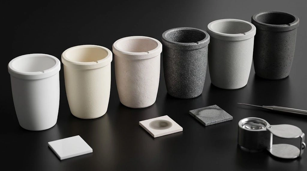
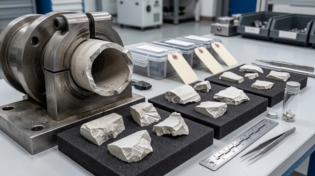
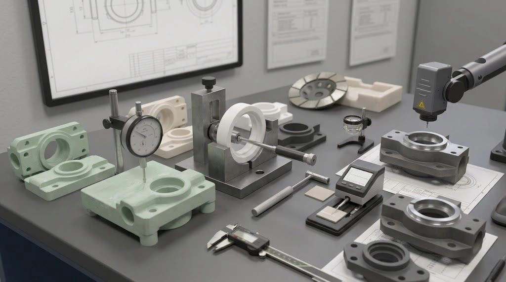
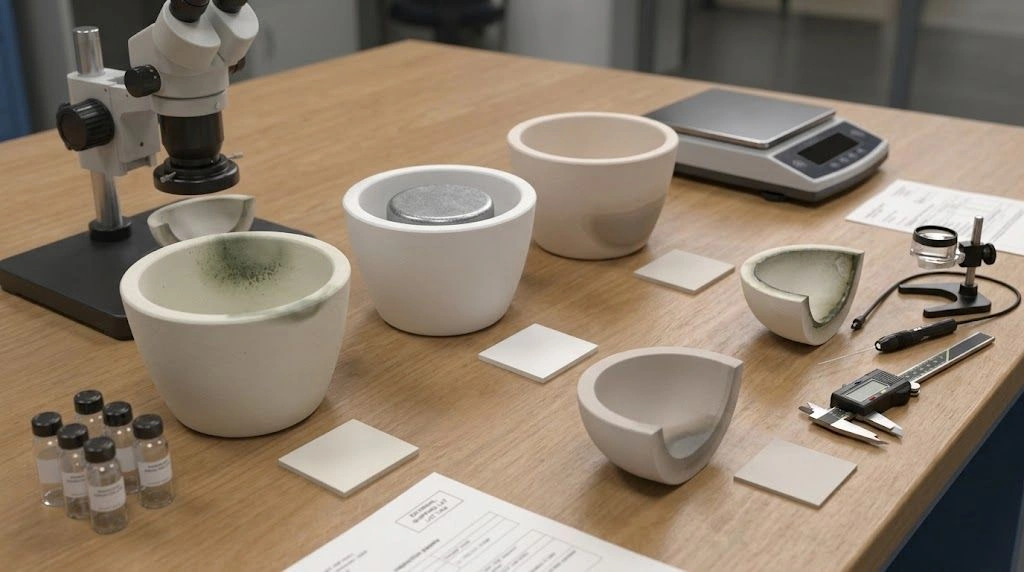
Ceramic tolerance and surface finish should be specified from function, not copied from a generic capability table. Identify the surfaces controlling fit, sealing, alignment, motion, wear, electrical spacing, or heat transfer. Decide whether each feature can remain as-fired, can be green-machined, or requires post-sinter grinding, lapping, or polishing. Keep size, GD&T, roughness, waviness, lay, and edge quality separate. Published tolerance and Ra capability depends on material, size, geometry, process, support, quantity, and inspection.
Start With the Functional Interface, Not a Tolerance Number
A seal face, locating bore, sliding guide, metering orifice, mounting datum, and noncontact exterior do not need the same precision. Before tightening a dimension, identify the failure it prevents and the mating feature that consumes the tolerance budget.
This logic drives drawing-based custom ceramic manufacturing services across custom technical ceramic parts such as rings, sleeves, discs, plungers, seals, and insulators: control functional characteristics and leave other surfaces at economical process capability.
| Precision class | Purpose | Typical examples | Specification direction |
|---|---|---|---|
| A — Functional closure | Directly determines assembly or performance | Seal face, shaft fit, metering bore, controlled gap | Calculate the limit and inspect it |
| B — Locating relationship | Establishes position or orientation | Mounting face, locating OD, bore axis | Use functional datums and GD&T |
| C — Process clearance | Prevents interference without controlling performance | Housing clearance, noncontact envelope | Allow economical process capability |
| D — Reference information | Explains geometry without defining acceptance | Derived overall size, duplicated model value | Mark as reference or remove |
A tight plus/minus size tolerance does not automatically control straightness, position, flatness, or sealing. Likewise, a low Ra value does not prove that a face is flat or that two faces are parallel. Complete the assembly tolerance stack first, then select the specification type that expresses the actual failure mode.
Ask these questions before adding precision:
- What happens at either limit, and which mating part uses the remaining budget?
- Does acceptance apply at room temperature or another defined condition?
- Is the surface bare or processed when inspected, and must the whole feature comply?
- Would a functional gauge express assembly more directly?
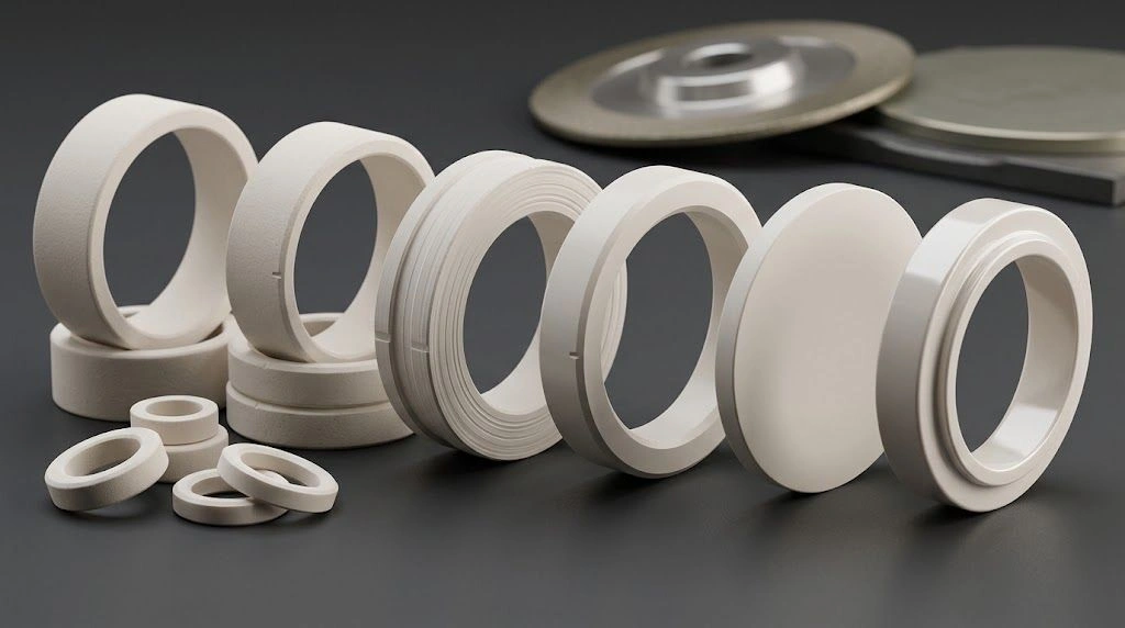
Physical process states show why precision and finish must be assigned feature by feature rather than inferred from one capability number.
Allocate Each Feature to the Correct Ceramic Process State
Ceramic geometry is created at several stages. Near-net forming and sintering may suit noncontact surfaces and generous clearances. Green machining can create holes, grooves, and profiles before full densification, reducing hard machining, but final dimensions still reflect material- and process-specific firing variation.
After sintering, dense ceramics usually require diamond grinding for close dimensions or geometric relationships. Lapping can improve suitable planar surfaces; polishing addresses finer asperities or specialized optical, sealing, cleanliness, or friction requirements. Coating, glazing, or metallization can alter final thickness and texture.
| Process state | Appropriate starting applications | Principal limitations | Cost direction |
|---|---|---|---|
| As-fired | Noncontact surfaces, envelopes, clearances, production geometry | Forming variation, shrinkage, distortion, draft, and camber | Lowest when function permits |
| Green-machined then fired | Passages, holes, grooves, and near-net complex features | Shrinkage compensation is required; firing variation remains | Can reduce hard grinding |
| Post-sinter ground | Datum faces, fits, diameters, thickness, position, and runout | Diamond tooling, access, setup, edge risk, and inspection | Higher; reserve for CTQs |
| Lapped | Low roughness, flatness, thickness, and parallel-face relationships | Extra handling, cleaning, and geometry constraints | Specialized finishing step |
| Polished | Optical, sealing, low-friction, or cleanliness-sensitive zones | Prior preparation, defect control, and specialized metrology | Use for verified function |
| Coated or metallized final state | Electrical, bonding, sealing, or environmental functions | Added thickness, adhesion, masking, and edge coverage | Inspect at the specified final state |
The same numerical tolerance can present different problems. A short, exposed OD may be easy to grind and gauge; a long, narrow bore can demand specialized tooling, fixturing, and inspection. A thin plate may change measured form with its support. These distinctions are part of advanced ceramic manufacturing capabilities, so supplier values are screening information, not automatic drawing limits.
Cost changes in steps: one tightened feature can add post-sinter grinding, lapping, fixturing, and inspection. Selective finishing is often economical—grind the datum and functional fit while leaving permissible noncontact surfaces as-fired.
Use these decision flips during review:
- If an exterior neither touches nor locates, evaluate an as-fired envelope.
- If a feature establishes a datum, fit, seal, or precise relationship, evaluate fired grinding.
- If a seal needs both texture and form control, review lapping after grinding.
- If optical or coating performance controls, develop an application-specific finishing specification.
- If deposition changes size or texture, state whether limits apply before or after it.
Separate Size, Form, Orientation, Location, and Surface Texture
Size, geometric tolerance, and surface texture describe different relationships. A size limit controls diameter, width, or thickness; it does not define flatness, axis straightness, hole location, or runout. Surface roughness describes smaller-scale profile variation, not overall form.
ASME Y14.5-2018 (R2024) supplies GD&T rules. ISO 1101:2017 provides ISO geometrical-tolerancing language, while ISO 5459:2024 addresses datums. These standards structure communication, not universal ceramic capability.
For texture, ASME B46.1-2019 (R2026) distinguishes roughness, waviness, and lay. ASME Y14.36-2018 (R2024) defines drawing designations. For ISO drawings, ISO 21920-1:2021 addresses profile-texture indications, and ISO 21920-2:2021 defines terms and parameters. State the governing edition rather than “latest ISO.”
| Functional need | Primary specification | What it does not control by itself |
|---|---|---|
| Finished diameter or thickness | Size limits | Location, orientation, or roughness |
| One face must not bow | Flatness | Parallelism to another face |
| Two faces must remain aligned | Parallelism or perpendicularity | Individual surface roughness |
| Hole pattern must assemble | Position from functional datums | Hole texture |
| Rotating feature must run true | Runout relative to a datum axis | Local roughness |
| Complex surface must follow design | Profile | Texture unless separately included |
| Seal or sliding texture | Ra, Rz, or another justified parameter | Flatness, waviness, and edge damage |
| Directional contact behavior | Lay direction | Size or form |
| Brittle edge acceptance | Chamfer or radius plus chip criteria | General surface roughness |
A ceramic face can be smooth but bowed, or flat with directional grinding lay. Two faces can each be flat but not parallel. A bore can meet diameter limits but be out of position. Low average roughness does not exclude isolated pits, scratches, chips, or near-surface damage. “Polished” defines neither a measurable limit nor acceptable defects.
Do not convert Ra and Rz with a universal ratio. Similar Ra can conceal different peaks and valleys. Choose a functional parameter, then define how and where it is measured.
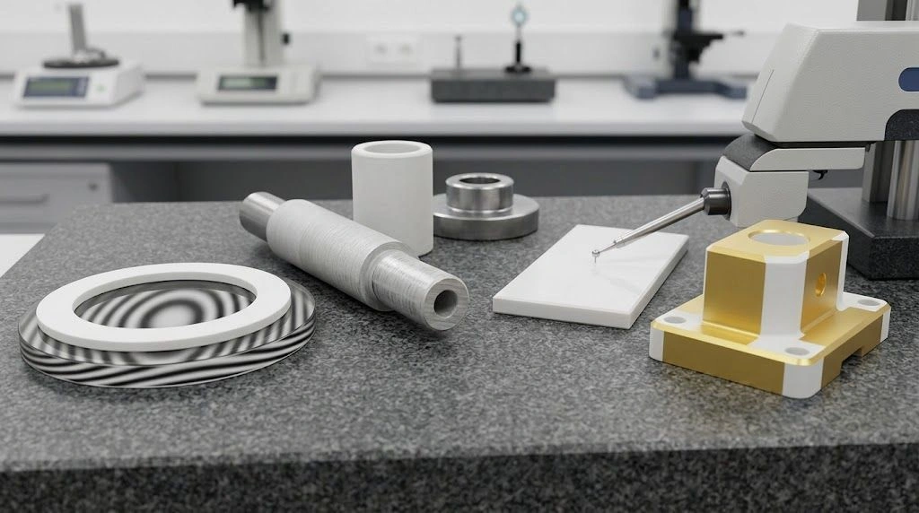
Real functional surfaces demonstrate that texture, flatness, lay, edge condition, and final coating state require separate controls.
Match Surface Finish to Sealing, Sliding, Wear, Coating, or Cleaning Function
Select finish from the contact mechanism and environment. A static seal may need roughness, flatness, waviness, lay, and edge controls. A sliding shaft may need texture plus diameter, straightness, or runout, while performance also depends on counterface, lubrication, load, speed, media, and contamination.
A wear surface may need specific topography, but lower Ra does not establish longer life. A bonding or metallization surface may need controlled texture and cleanliness rather than optical polish. Cleanliness-sensitive surfaces also need residue and defect controls. Optical surfaces require a separate figure, defect, aperture, coating, and metrology specification.
| Surface function | Requirements to consider | Common specification error |
|---|---|---|
| Static seal face | Roughness, flatness, waviness, lay, and edge zone | Specifying only Ra |
| Sliding guide | Texture, diameter, straightness, counterface, and lubrication | Requesting “mirror finish” without tribology review |
| Wear surface | Texture, geometry, contact stress, and abrasive environment | Assuming lower Ra always means longer life |
| Mounting datum | Flatness, contact area, and perpendicular relationships | Polishing a surface that only needs stable location |
| Fluid bore | Diameter, straightness, functional length, and texture | Applying one tight condition through unnecessary depth |
| Metallized surface | Preparation, cleanliness, adhesion, and final thickness | Inspecting only the bare ceramic |
| Bonding surface | Texture, chemistry, flatness, and bond-line requirement | Automatically specifying optical polish |
| Optical surface | Figure, texture, defects, coating, and clear aperture | Treating it as an ordinary mechanical finish |
| Noncontact exterior | Envelope and visual acceptance | Grinding or polishing the entire part |
Grinding is primarily used to establish final dimensions and geometry, but wheel selection and process conditions also affect the surface and near-surface region. ASTM C1495-16(2023) evaluates how a specified surface-grinding process affects the flexure strength of advanced-ceramic specimens. Its scope supports treating grinding damage as a process risk, not assuming every ground surface is equivalent. It concerns controlled planar specimens and should not be presented as certification of finished-component strength or service load capacity.
Lapping and polishing are not interchangeable. Lapping commonly uses loose abrasive against a plate to improve texture and form; polishing targets smaller-scale asperities after suitable preparation. The route depends on material, geometry, prior surface, cleanliness, and metrology. PremaTech’s lapping and polishing overview illustrates the manufacturing distinction.
Do not claim that polishing eliminates grinding damage, one finish guarantees sealing, or smoother ceramic is automatically stronger. Specify preparation, defect criteria, inspection, and component-level validation.
Define the Measurement Basis and Build the RFQ Package
A tolerance is incomplete if customer and supplier can use different setups and reach conflicting results. For every CTQ, define final state, datum setup, support, zone, method, sampling, and report. A CMM may suit a datum-related pattern or profile, while micrometers, air gauges, profilometers, flatness equipment, or functional gauges may be more direct elsewhere.
For a surface-texture callout, identify:
- governing standard and edition, parameter, units, and limit type;
- direction relative to lay and required filtering or evaluation conditions;
- functional area, excluded edges, and trace locations;
- contact or optical method; and
- inspection state before or after cleaning, coating, glazing, or metallization.
Contact and optical methods can respond differently to steep features, reflectivity, pores, and filtering. The method and analysis must match the contract. For thin geometries, define support and clamping conditions that may affect form.
Where uncertainty is significant, agree on a conformity rule. ISO 14253-1:2017 establishes decision rules for geometrical specifications that consider measurement uncertainty. Set the rule before inspection.
| RFQ item | Information to provide | Supplier response expected |
|---|---|---|
| Design authority | Current 2D drawing, 3D model, revision, and source of truth | Confirmation of reviewed revision |
| Material | Ceramic type, grade, and required documentation | Proposed grade and exceptions |
| Functional CTQs | Failure mode, mating feature, and tolerance stack | Feature-specific capability review |
| Process state | As-fired, green-machined, ground, lapped, polished, coated, or metallized zones | Proposed route and stock strategy |
| Geometry | Size limits, GD&T, datum scheme, and functional depth or land | Manufacturability and datum feedback |
| Surface | Parameter, standard, direction, zone, and defect limits | Measurement method and exceptions |
| Inspection | Setup, support, gauges, sampling, reports, and decision rule | Inspection plan and charges |
| Commercial scale | Prototype and production quantities | Tooling, fixtures, lead-time assumptions, and alternatives |
| Handling | Cleaning, packaging, and surface protection | Proposed controls and traceability |
Connect these requirements to the supplier’s ceramic quality assurance process. Request appropriate first-article dimensions, designated texture results, material certificates, and drawing-revision traceability. Define edge chamfers or radii and quantitative chip limits; “no chips” is too ambiguous for consistent inspection.
The supplier review should identify each CTQ’s process state, capability exceptions, datum changes, cost drivers, marked alternatives, and tooling or inspection assumptions. A tolerance may be relaxed, localized, or replaced with a functional control without weakening design intent.
Send the drawing, material, quantities, mating information, CTQs, final surface state, and inspection expectations. The best specification is the least restrictive combination of size, geometry, texture, edge, and verification controls that closes the function.
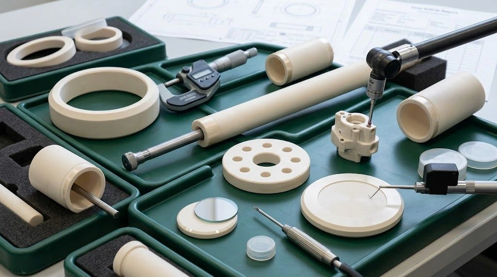
A feature-specific inspection plan connects the drawing, final process state, measurement setup, and acceptance record.
Frequently Asked Questions
What tolerances can technical ceramic parts hold?
There is no single valid value for every ceramic part. Achievable tolerance depends on material grade, feature size, geometry, aspect ratio, access, process state, quantity, support, and inspection method. Ask for a feature-specific capability review against the controlled drawing instead of applying a supplier’s best demonstrated value universally.
What is the difference between as-fired and ground ceramic tolerance?
As-fired dimensions retain forming, shrinkage, and firing variation and are economical where the function permits. Post-sinter grinding removes controlled stock from dense ceramic to create closer sizes or geometric relationships. The appropriate route depends on the individual feature; one part can combine as-fired exteriors with selectively ground CTQs.
Is Ra the same as flatness?
No. Ra describes average profile roughness at a comparatively small scale under defined measurement conditions. Flatness controls the overall form of a surface without reference to a datum. A face can have low Ra and still be bowed, so sealing applications may require both texture and flatness controls.
What is the difference between grinding, lapping, and polishing ceramic?
Diamond grinding commonly establishes final size and geometry after sintering. Lapping uses a controlled abrasive process to improve suitable surfaces in texture, flatness, thickness, or parallelism. Polishing targets finer-scale surface condition for a specific function. They are sequential options only when the material, geometry, and requirement justify them.
How should ceramic surface finish be specified?
State the governing standard and edition, parameter, units, limit type, measurement direction, filtering or evaluation conditions, functional zone, instrument method, and number of traces. Also define the final process condition, lay or defect limits when relevant, and separate roughness from flatness, waviness, geometry, and edge acceptance.
What should a ceramic-part RFQ include?
Provide controlled drawings and models, material grade, quantities, feature functions, mating information, CTQs, datum scheme, size and GD&T limits, surface-texture callouts, final coating or metallization state, edge criteria, inspection and sampling requirements, certificates, and packaging needs. Ask the supplier to identify exceptions, alternatives, and major cost drivers.