A ceramic-part drawing is ready for supplier release when it defines one governing revision, a controlled material grade, functional geometry, assembly-based datums, CTQ tolerances, surface and edge requirements, and feasible inspection methods—without contradictions between the 2D drawing, 3D model and notes. Review every feature through blank formation, green machining, sintering, post-sinter diamond finishing and final inspection. Do not apply metal-part general tolerances automatically. Tighten only the characteristics controlling fit, sealing, alignment, motion, electrical spacing or load, and send unresolved manufacturing assumptions for supplier review before tooling or prototype approval.
Is the Governing Package, Function and Material Clearly Defined?
Begin before checking individual dimensions. Confirm the part and drawing numbers, revision, units, projection method and applicable specification convention. When a 2D drawing and 3D model both define geometry, identify which governs and how conflicts are resolved. Remove superseded files, duplicate dimensions and inherited notes that could authorize different interpretations.
Use custom ceramic manufacturing services as the review route once the current package is assembled. If the material family remains open, compare the operating failure mode through the technical ceramic material matrix before freezing the grade.
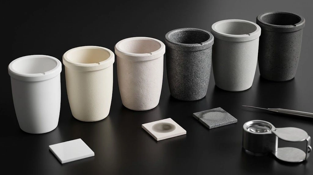
“Alumina,” “zirconia” or “silicon nitride” may be too broad when grade-dependent chemistry, stabilizer, density, porosity, color or electrical behavior matters. State the controlled grade or define functional property boundaries for supplier review. Link the drawing to temperature, atmosphere, media, loading, wear, mating materials and cleaning conditions without crowding every application detail into geometry notes.
Complete this initial release checklist:
- Confirm part number, drawing number and current revision.
- Declare whether the 2D drawing or 3D model controls.
- Define units, projection and drawing-standard edition.
- Specify the ceramic grade, not only the material family.
- State prototype, first-article and recurring quantities.
- Identify mating components and functional interfaces.
- Mark CTQs for fit, sealing, alignment, load or insulation.
- Record service temperature, atmosphere, media and cycle.
- Define certificates, reporting and lot traceability.
- Remove conflicts, obsolete notes and uncontrolled files.
The review objective is not a drawing containing the most dimensions. It is one source of truth that tells design, manufacturing and inspection what must function, what may vary and which questions remain subject to process review.
Which Process State Creates Each Feature?
A ceramic feature cannot be judged only at final nominal size. Review it through blank forming, green machining, sintering, hard finishing and inspection. A feature made before firing is exposed to formulation- and geometry-dependent shrinkage and distortion. A feature finished afterward needs grinding stock, diamond-tool access, stable fixturing and measurement access.
Green machining can form profiles, bores and reliefs while the body is easier to cut. The manufacturer must compensate its own controlled material and process. Precision Ceramics says ceramics generally shrink by about 20% during sintering and notes that some precision drilling or grinding may occur after firing (green-machining overview). Treat that percentage as illustrative—not a drawing allowance or universal rule.
| Feature | Pre-sinter review | Sintering risk | Post-sinter review | Release decision |
|---|---|---|---|---|
| External profile | Blank allowance and access | Shrinkage, bow or twist | Grinding stock and wheel access | As-fired or finish-ground |
| Thin wall/web | Handling strength and uniformity | Differential shrinkage | Support and chipping | Retain, thicken or redesign |
| Internal corner | Tool radius | Stress concentration | Wheel access | Add acceptable radius |
| Through bore | Green tooling and straightness | Bore distortion | Honing or ID-grinding access | Size, depth and process state |
| Blind bore | Bottom shape and depth | Local distortion | Tool overtravel and gauging | Clarify bottom and finish |
| Thread | Green form and engagement | Pitch distortion and fragile crests | Grinding/tapping feasibility | Supplier review |
| Seal face | Datum and stock allowance | Warpage | Grinding or lapping | Texture and flatness |
| Large flat part | Handling and firing support | Warpage | Grinding setup | Function-based flatness |
Flag abrupt section changes, deep small holes, intersecting bores, undercuts, asymmetric masses and unsupported edges. Where function permits, increase internal radii, add controlled chamfers, make wall transitions gradual and provide tool relief. A feature that can be modeled is not automatically formable, finishable or inspectable.
Do not publish a universal minimum wall, bore or radius. Capability changes with material, part scale, aspect ratio, forming route, quantity, finish and equipment. The drawing should control final functional geometry while leaving proprietary shrinkage compensation and intermediate dimensions with the manufacturer unless responsibility is explicitly agreed.
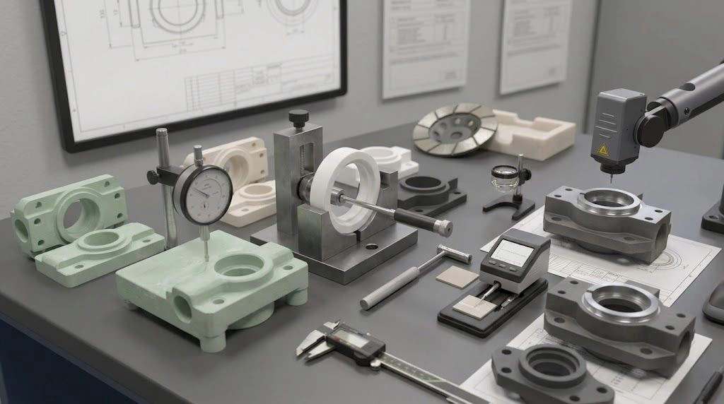
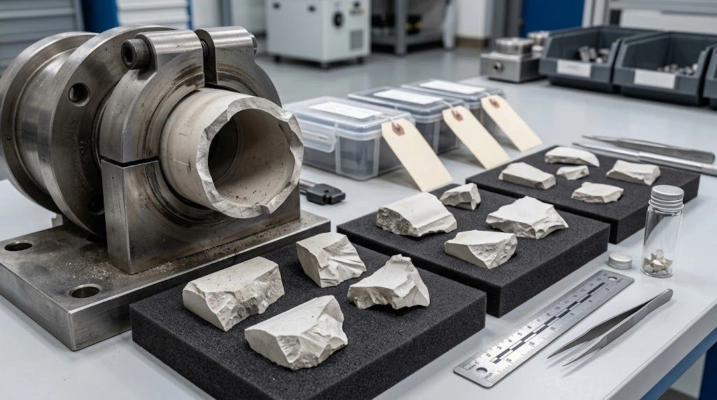
Process-state samples show why the same final feature creates different risks before firing, during sintering and after hard finishing.
Are Datums, Tolerances, Surface Texture and Edges Functional?
Select datums that reproduce how the part locates in its assembly. A datum feature must also be stable, accessible and measurable in its specified final state. If a rough as-fired face cannot establish a repeatable orientation, create a selectively ground datum land or change the scheme. Avoid datum chains that are theoretically complete but impossible to fixture without rocking or edge loading.
ASME Y14.5-2018 (R2024) and ISO 1101:2017 provide geometric specification languages. ISO 5459:2024 covers datums and datum systems. These standards define communication and interpretation; they do not establish a ceramic supplier’s achievable tolerance.
Avoid tight bilateral limits on every dimension. Control size, position, orientation and form where they close a functional tolerance stack. Let noncritical surfaces follow an agreed as-fired or supplier-reviewed envelope. Verify worst-case assembly conditions and remove redundant controls that can conflict or demand unnecessary finishing.
A blanket reference to ISO 2768-1:1989 needs explicit review. Its published scope applies to dimensions of workpieces produced by metal removal or formed from sheet metal. It should not automatically govern every as-fired ceramic characteristic. State a material- and process-appropriate general tolerance agreement, then apply individual limits to CTQs.
Surface texture, flatness, waviness and visual defects are different requirements. ASME B46.1 covers roughness, waviness and lay; ASME Y14.36 addresses drawing designations. For a functional zone, define the parameter—such as Ra or Rz—limit, measurement direction, cutoff/filter and method where results are sensitive. “Smooth,” “polished” and “mirror finish” alone are not acceptance rules.
Audit the drawing with these questions:
- Does the datum sequence reproduce assembly location?
- Will every datum exist in its required final process state?
- Can a fixture or probe contact it without rocking or damage?
- Are tight tolerances limited to functional characteristics?
- Are size, position, form and orientation controls consistent?
- Are basic, reference and inspection dimensions distinguished?
- Has the worst-case tolerance stack been checked?
- Is each surface parameter tied to a defined zone and method?
- Are texture, flatness, waviness and visual quality separate?
- Are chamfers, radii and permitted chips measurable by zone?
Replace “break all sharp edges” or “no chips” with controlled geometry and inspection conditions. Distinguish protected sealing or locating edges from nonfunctional edges, and state magnification or lighting when visual acceptance depends on them.
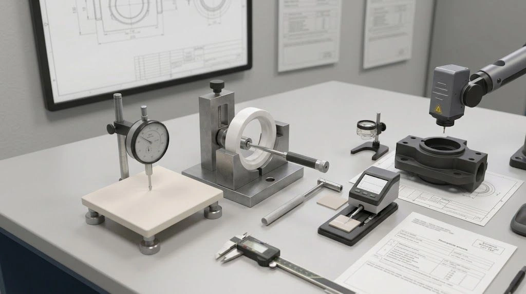
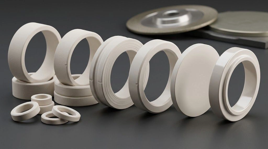
Functional datums and measurable surface zones connect drawing language to a repeatable inspection setup.
Can Every CTQ Be Manufactured and Inspected Reproducibly?
A requirement is incomplete when conformity cannot be evaluated. Build a CTQ-to-inspection matrix naming the characteristic, datum setup, final process state, instrument, fixture, measurement zone, sampling and required report. Confirm access before specifying full-depth bore size, internal position, deep texture or a datum hidden after assembly.
| CTQ | Drawing input | Inspection question | Evidence |
|---|---|---|---|
| Bore diameter | Limits, depth and process state | Is the complete controlled depth accessible? | Values or bore report |
| Bore position | Datums and evaluation depth | Is the setup repeatable? | CMM or optical report |
| Seal-face flatness | Tolerance and zone | Is support-induced bending controlled? | Flatness map |
| Surface roughness | Parameter and conditions | Is trace direction defined? | Profilometer report |
| Edge quality | Zone, chamfer and chip limit | Are lighting and magnification agreed? | Visual record |
| Material grade | Controlled designation | Which certificate or test verifies it? | Material CoC |
| Density/porosity | Method and functional limit | Is the method suitable for the grade? | Test certificate |
| Assembly fit | Mating condition or gauge | Can a functional fixture reduce ambiguity? | Gauge/assembly report |
Use CMM, optical measurement, air gauging, bore gauges, profilometry, flatness mapping or a functional fixture according to the characteristic—not prestige. Contact measurement may damage an edge or alter a delicate setup; optical results depend on edge-detection and filtering conventions. Do not require CMM inspection for every dimension when a simpler calibrated method answers the acceptance question.
When measurement uncertainty is significant relative to the tolerance, agree on a conformity decision rule. ISO 14253-1:2017 establishes rules for verifying conformity or nonconformity with geometrical specifications while accounting for measurement uncertainty.
Hard grinding also deserves process control. ASTM C1495-16(2023) compares advanced-ceramic flexural specimens after a user-specified surface-grinding process with a baseline. It supports reviewing grinding direction, stock removal and damage, but it is not a finished-component acceptance specification. Coupon flexural results cannot become a guaranteed load rating for a complex part.
Review shaping, sintering, grinding, lapping and polishing through the advanced ceramic manufacturing capabilities relevant to the actual geometry. Reserve hard finishing for datums and CTQs that create measurable assembly or performance value.
What Review Status and First-Article Package Should Be Released?
Do not close review with informal comments distributed across email threads. Give the package one disposition and maintain an issue log containing the feature, drawing reference, risk, owner, due date and final decision.
| Status | Meaning | Required next action |
|---|---|---|
| Pass | Package is defined for the agreed quotation or production stage | Release controlled files |
| Clarify | Missing or conflicting information prevents interpretation | Drawing owner corrects the package |
| Supplier Review | Requirement is clear but ceramic-process capability is unresolved | Supplier proposes route, tolerance or test |
| Redesign | Geometry or requirement creates unacceptable risk | Engineering changes the design |
Approve redlines formally, update the revision and remove superseded files. For prototypes and first articles, freeze the material grade and substitute rules; governing 2D/3D files; manufacturing route and finish state of each CTQ; inspection methods and decision rules; certificates and first-article report; cleaning, marking and packaging; approved deviations and expiration; and repeat-production change-notification requirements.
First-article evidence should report actual CTQ results rather than only “pass.” It must identify the drawing revision, units, method, datum setup, sample quantity and any deviation. Connect inspection planning, material documentation and traceability to the ceramic quality assurance process. A certificate of conformity does not replace measurement evidence specifically required by the drawing or purchase order.
For sample-based replacement, treat the old component as evidence, not the design authority. Wear, fracture, coating loss or prior repair may hide original geometry. Supply multiple samples when possible, mating-part dimensions, installation information and service history. Separate measured features from inferred nominals on a reconstructed drawing, then approve it before production.
Submit the current 2D drawing, 3D model, material or service conditions, quantities, CTQ list and inspection requirements for manufacturability review. Release only when assumptions are visible, responsibilities are assigned, and the approved revision can be manufactured, inspected and repeated without relying on undocumented interpretation.
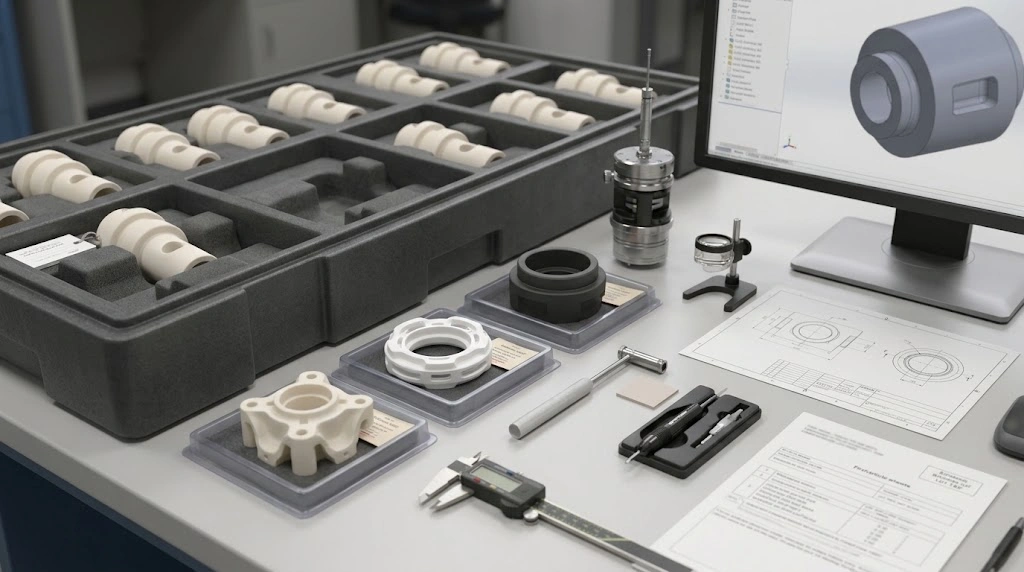
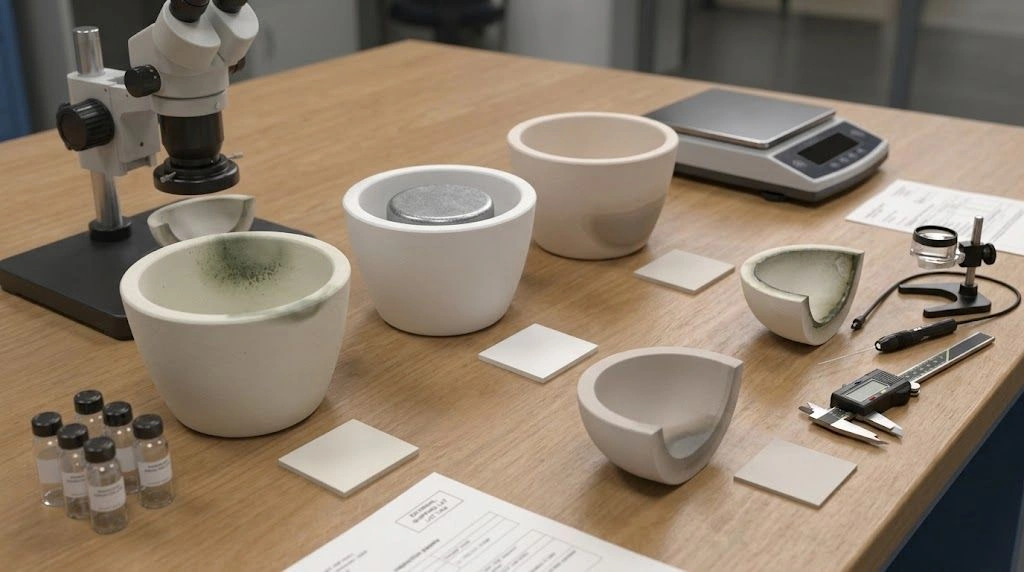
A controlled release package closes the material, process state, CTQs, inspection evidence and approved revision before repeat production.
Frequently Asked Questions
What is the minimum package for a custom ceramic-part RFQ?
Provide the current 2D drawing, available 3D model, material grade or operating conditions, prototype and production quantities, CTQ list, service environment and required inspection documents. State whether the drawing or model governs and identify unresolved features that require supplier review.
Should the 2D drawing or the 3D model govern?
Either can govern, but the package must identify the controlling source. The 2D drawing commonly carries tolerances, datums, surface requirements, notes and inspection information, while the model communicates nominal geometry. Resolve every known conflict and synchronize revisions before release.
Should sintering shrinkage be added to the customer drawing?
Normally, the customer drawing defines required finished geometry. The ceramic manufacturer calculates green dimensions and shrinkage compensation for its controlled formulation and process. Do not add a generic percentage unless responsibility, material, forming route and calculation basis are explicitly agreed.
Can ISO 2768 general tolerances be applied to ceramic parts?
Not automatically. ISO 2768-1’s published scope addresses dimensions produced by metal removal or sheet-metal forming. Review as-fired ceramic features separately and agree on process-appropriate general tolerances. Apply explicit limits to CTQs rather than relying on a blanket title-block note.
How should ceramic surface finish be specified?
Identify the functional surface, texture parameter, numerical limit, measurement direction, cutoff or filter and inspection method where necessary. Keep roughness separate from flatness, waviness, polish appearance and edge defects. Terms such as “smooth” or “mirror finish” are insufficient alone.
Can an obsolete ceramic component be reproduced from a sample?
It can be evaluated, but wear or fracture may conceal original geometry and tolerances. Provide multiple samples, mating dimensions, service conditions and failure history when available. Approve a reconstructed drawing that distinguishes measured features from inferred nominal requirements before manufacture.