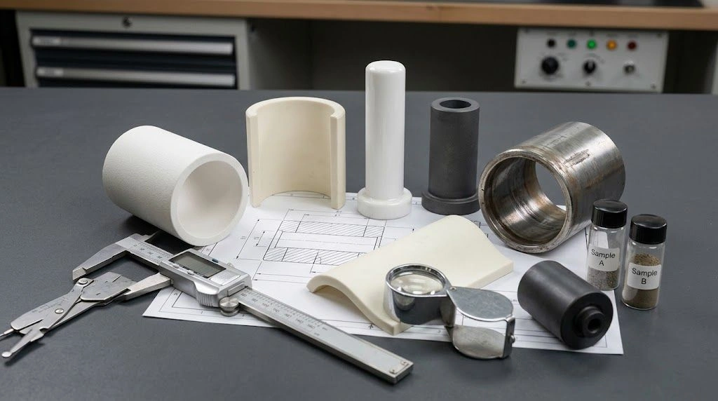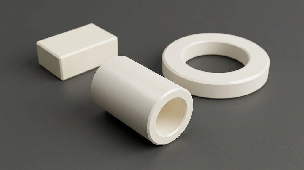
A zirconia tube cracks during grinding when tensile stress at an existing or grinding-created flaw exceeds the tube’s local resistance to crack growth. The initiating condition may be excessive grinding force or heat, a loaded or uneven diamond wheel, poor coolant access, chuck-induced ovalization, an unsupported thin wall, uneven grinding stock, or a pore or crack already present in the sintered blank. Zirconia phase transformation can change the residual-stress state, but it does not make grinding damage harmless. Diagnose the problem from crack timing, origin, orientation, process records and controlled trials—not from one roughness value or machine setting.
1. Start With Crack Timing, Location and Orientation
“Cracked during grinding” is imprecise. Record whether the crack first appeared at wheel entry, roughing, finishing, spark-out, coolant interruption, unloading, cleaning or later inspection. A flaw may grow under the wheel and open only after fixture release.
Preserve every fragment before cleaning the fracture. Photograph the tube, fracture faces, fixture orientation and grinding zone. Relate the origin to the chuck, collet, mandrel, support, tube end, shoulder, hole, thin wall, maximum-stock zone and coolant direction.
ASTM C1322-25 provides a consistent practice for locating and characterizing fracture origins in brittle ceramics. It also warns that one or a few specimens can mislead and that component interpretation may be difficult. Combine fracture markings with fabrication and machining records. Send the failed part, drawing and process history for custom ceramic engineering support when needed.
| Observation | Priority hypotheses | Evidence to check first |
|---|---|---|
| Crack begins near a jaw or chuck | Point loading, excessive grip, ovalization, misalignment | Contact pattern, grip setting, runout |
| Circumferential crack near a support edge | Bending, short support or abrupt load transfer | Support length, overhang, fixture geometry |
| Longitudinal crack | Hoop stress, wall variation, ID support or axial flaw | Wall map, roundness, bore condition |
| Crack follows a shoulder or step | Stress concentration, uneven stock, restricted wheel access | Radius, stock transition, wheel path |
| Multiple chips at a tube end | Entry/exit impact, edge damage or axial loading | Chamfer, engagement direction, handling |
| Crack appears after unloading | Residual stress, springback or fixture release | In-fixture and released measurements |
| Random locations within one lot | Blank variability, pores, density or mixed conditions | Lot records and unused controls |
| Same location on one machine | Systematic fixture, wheel, coolant or machine cause | Runout, balance, nozzle, support |
These patterns route the investigation; they do not prove cause.
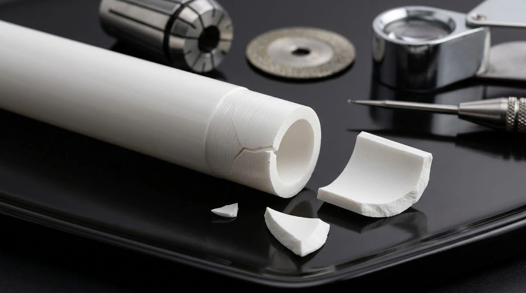
Preserving the tube, fracture surfaces and setup relationship allows crack timing and origin evidence to guide the investigation.
2. Separate an Incoming Blank Problem From Grinding Damage
Grinding can create a new surface or subsurface flaw, expose an existing flaw, or raise stress at an incoming defect until it becomes critical. Do not equate fracture during machining with proof that machining created the initiating defect.
A sintered tube may contain pores, agglomerates, inclusions, density variation, residual stress, bow, eccentricity or uneven stock. Freeze material and batch identity. Stabilizer chemistry and content, grain size, density, phase distribution and thermal history can change damage behavior.
Inspect representative blanks before grinding. Record OD/ID roundness, straightness, circumferential and axial wall thickness, concentricity, stock, edges and previous machining. Use a validated crack-detection method where appropriate and retain an unused same-lot tube.
NIST scratch-damage research found different contact and subsurface-damage responses in Mg-PSZ, Y-TZP and Ce-TZP. Its blocks and bars were not industrial tubes, so the data do not define tube parameters; they show why results should not transfer automatically between zirconia systems. The technical ceramic material matrix provides family context, while production behavior remains grade- and process-specific.
| Evidence | Incoming-condition signal | Grinding contribution signal |
|---|---|---|
| Crack documented before grinding | Strong | Not required |
| Similar internal flaw in unused same-lot tube | Strong | May still interact with grinding |
| Failure locations vary randomly within one lot | Possible material or stock variation | Check machine and setup variation |
| Fracture repeatedly starts at fixture contact | Less likely as the sole cause | Strong workholding signal |
| Crack follows fresh grinding grooves | Existing flaw may intersect the surface | Grinding-origin candidate |
| Damage depth changes with removal severity | Less likely as the sole explanation | Supports grinding contribution |
| Failure stops after fixture or wheel correction | Does not eliminate hidden blank flaws | Supports process contribution |
| Failure follows only one material or sintering lot | Strong batch candidate | Audit coincident process changes |
Review blank and grinding evidence in parallel. A correction is incomplete if it improves machining but leaves uncontrolled stock or sintering variation.
3. Check Whether Workholding Distorts or Point-Loads the Tube
Thin-wall tubes can change roundness while clamped. A chuck, collet or mandrel may impose hoop stress or constrain a distorted blank. Geometry ground under constraint can change after release. Dirt, damaged jaws, short contact, hard edges, overhang and axial restraint can add bending or point loads.
Measure runout and roundness before clamping, while clamped where practical, and after release. Record fixture type, contact length, grip control, support spacing, mandrel condition, axial restraint and overhang. Inspect witness marks for concentrated contact.
A study of thin Y-TZP plates found that residual stress and bending deformation varied with thickness and grinding conditions. Plates are not tube models, but the work supports treating thin-section deformation and grinding stress as coupled; tube curvature and fixture restraint add variables.
| Workholding check | Evidence to record | Risk indication |
|---|---|---|
| Fixture type | Chuck, collet, mandrel, centers or centerless support | Different radial and axial load paths |
| Contact length | Actual supported span and grinding-zone distance | Short support or excessive overhang |
| Grip condition | Controlled setting and repeatability | Variable or excessive constraint |
| Contact surface | Cleanliness, damage and witness pattern | Local hard contact or misalignment |
| Runout | Free-state and clamped readings | Eccentric setup or distorted blank |
| Ovalization | Roundness change in the fixture | Chuck- or mandrel-induced deformation |
| Axial constraint | Stops, shoulders and thermal freedom | Added axial tensile stress |
| Internal support | Mandrel clearance and contact distribution | Local expansion or bore loading |
| Unloading response | Geometry and crack condition after release | Springback or stress release |
Do not solve workholding with a universal clamping-force value. Confirm the setup using in- and out-of-fixture geometry, repeatability and failure-location evidence for the actual tube.
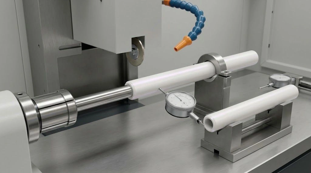
Fixture contact, overhang, internal support and clamped-versus-released geometry must be checked together.
4. Audit the Wheel, Coolant, Machine and Grinding Sequence
Diamond grinding removes zirconia through interacting deformation and brittle-fracture mechanisms. The result depends on the material grade, grit and bond, wheel sharpness, contact force, heat removal, vibration, residual stress and any transformation near the surface.
Audit the full system. Record wheel specification, grit, concentration, bond, profile, edge, dressing, accumulated use, loading, balance and spindle runout. Capture wheel and work speeds, infeed, traverse, dwell, spark-out, allowance and the roughing-to-finishing sequence.
For coolant, document chemistry, concentration, temperature, flow, filtration, nozzle location and contact access. A high pump setting does not prove fluid reaches a shielded or ID grinding zone. Record interruptions, swarf and temperature drift; review machine stiffness, vibration and alignment.
ASTM C1495-16(2023) states that surface grinding can introduce microcracks and other near-surface changes and can reduce flexural strength depending on the process and material response. It applies to methods that generate planar surfaces and is not directly applicable to cylindrical or centerless grinding. Use it as mechanism and process-control guidance, not as a tube acceptance standard.
| Process symptom | Possible mechanism | Verification route |
|---|---|---|
| Rising power or grinding force | Wheel loading, dull grit or excessive removal | Trend data, dressing and wheel inspection |
| Crack follows coolant interruption | Thermal gradient acting at a flaw | Coolant log and fracture position |
| Discoloration or vapor at contact | Rubbing or inadequate heat removal | Nozzle access and wheel condition |
| Periodic surface marks | Wheel imbalance, runout or vibration | Frequency and rotational correlation |
| End chipping at wheel entry | Abrupt engagement or unsupported edge | Approach path, chamfer and support |
| Failure rises after several parts | Loading, dressing drift or coolant contamination | Part sequence and maintenance history |
| Roughness improves while cracking rises | Surface metric hides deeper damage | Microscopy and controlled sectioning |
| Crack rate varies by shift | Setup, dressing, handling or record variation | Standardized audit by operator and lot |
Why Phase Transformation Does Not Give a Simple Answer
Tetragonal-to-monoclinic transformation can create local compression in some zirconias while grinding introduces scratches, cracks, pullout and stress gradients. Whether compression shields the controlling flaw depends on grade, transformation depth, flaw depth and later loading.
An open-access dental Y-TZP study reported both transformation-related compression and grinding-created defects. Its specimens and diamond-bur method cannot establish an industrial tube window. A broader zirconia transformation review reinforces the importance of composition, stabilization and process control.
Do not interpret increased monoclinic phase as automatic proof of strengthening or damage. Low surface roughness likewise cannot exclude a deeper crack.
5. Validate Corrective Actions With a Controlled Trial
Changing everything at once may reduce scrap without identifying the effective correction. Establish one grade and lot, defined incoming geometry and stock, one fixture, documented wheel condition, stable coolant, recorded settings and a fixed inspection sequence.
Change one primary factor at a time or use a structured design. Record crack incidence, origin, edge chips, released roundness, wall range, surface texture, yield, wheel condition and available power or force. Add justified microscopy, sectioning, phase or stress analysis for high-risk parts.
Use this corrective-action order:
- Confirm zirconia grade, batch and incoming blank condition.
- Map wall thickness, straightness, roundness and grinding stock.
- Remove fixture point loads and measure clamped distortion.
- Restore wheel balance, runout, sharpness and dressing control.
- Confirm coolant reaches the active contact consistently.
- Test removal severity and roughing-to-finishing distribution.
- Protect tube ends, shoulders and thin transitions.
- Standardize loading, handling and unloading.
- Repeat the accepted trial across parts, wheel life and setups.
| Trial output | Baseline | Corrective trial | Acceptance basis |
|---|---|---|---|
| Tubes processed | Agreed minimum sample | ||
| Visible crack rate | Project criterion | ||
| Edge-chip rate | Drawing or visual criterion | ||
| Released roundness | Drawing requirement | ||
| Wall-thickness range | Drawing requirement | ||
| Surface texture | Functional-zone requirement | ||
| Power or force trend | Stable project-defined range | ||
| Wheel condition | No abnormal loading or damage | ||
| Coolant condition | Recorded flow, access and temperature | ||
| Microscopy findings | No prohibited damage | ||
| Dimensional yield | Agreed production target |
One successful tube does not prove stability. Verify repeatability within the lot, across loading cycles and the intended wheel-use interval, and after fixture release. Define escalation triggers.
Reference advanced ceramic manufacturing capabilities when reviewing how forming, sintering, stock control and precision grinding interact. Connect incoming checks, in-process records and final acceptance through the ceramic quality assurance process.
For a supplier corrective-action or RFQ handoff, provide the controlled part drawing; zirconia grade, stabilizer and lots; pre-grind OD, ID, wall, bow and stock map; grinding type; machine and wheel specification; dressing history; fixture and support details; coolant condition; settings by operation; crack timing, location and photographs; unused controls; inspection method; and trial acceptance rules. Clearly separate confirmed evidence from hypotheses.
| Handoff group | Minimum controlled record |
|---|---|
| Part and material | Part revision, zirconia/stabilizer, material lot, sintering lot, previous operations |
| Incoming geometry | OD, ID, wall map, roundness, bow, concentricity and grinding stock |
| Grinding system | Machine ID, operation, wheel specification, dressing history and settings |
| Support and coolant | Fixture contacts, overhang, clamped geometry, nozzle access and coolant condition |
| Failure evidence | First-visible step, part sequence, crack origin, orientation, photographs and preserved fragments |
| Corrective trial | Factor changed, controlled constants, sample size, measurements and acceptance decision |
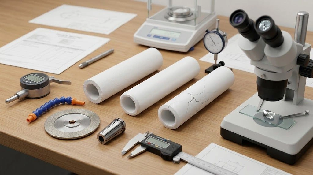
A controlled trial links blank condition, fixture, wheel, coolant and process records to measurable acceptance evidence.
Frequently Asked Questions
Does grinding always weaken zirconia?
No. Grinding can introduce flaws, residual stress, phase transformation and surface changes whose net effect depends on the zirconia grade and grinding system. Results from one specimen type cannot approve a tube process. Inspect the controlling flaw and validate the finished component under its intended requirements.
Why does a zirconia tube crack near the chuck?
A crack near the chuck prioritizes point loading, excessive constraint, jaw misalignment, dirt, short contact, ovalization and unsupported overhang. Compare free and clamped roundness and runout, inspect witness marks, map the fracture origin and repeat the setup before assigning the failure to grip force alone.
Can coolant prevent zirconia grinding cracks?
Coolant can remove heat and swarf, but its presence does not guarantee crack prevention. Chemistry, temperature, flow stability, filtration, nozzle position and access to the active contact all matter. Verify delivery at the grinding zone and investigate wheel condition, force, geometry and incoming flaws in parallel.
Does tetragonal-to-monoclinic transformation cause the crack?
Not by itself. Transformation may contribute local compression, while grinding can simultaneously create scratches, deeper cracks and stress gradients. The net effect depends on material grade, transformed-layer depth, flaw geometry and later loading. Phase content must therefore be interpreted with fractography and process evidence.
Can annealing heal a cracked zirconia tube?
Do not assume so. Heat treatment may change residual stress or phase content, but it cannot be treated as guaranteed removal of a deep crack. A visibly cracked or otherwise nonconforming tube should follow the approved disposition process, with any recovery route separately engineered and validated.
How should a revised zirconia grinding process be validated?
Hold the grade, blank range, fixture, wheel condition, coolant and inspection sequence under control. Change one primary factor or use a structured design. Compare crack rate, origin, released geometry, surface and subsurface evidence, process trends and yield across enough parts and setups to test repeatability.