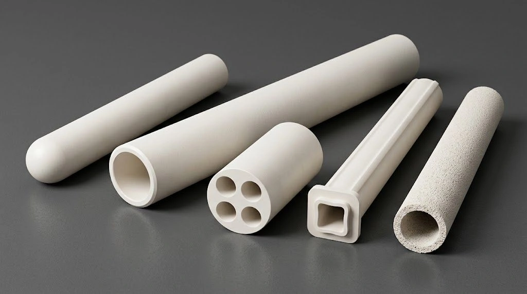
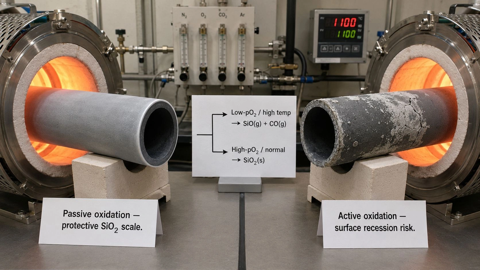
Impact resistant alumina tube plays a crucial role in preventing mechanical failures in automation environments where collisions, tool drops, and high-speed transfers frequently occur. Its enhanced fracture toughness, fine-grain microstructure, and optimized mounting design can support longer service life versus standard alumina tubes in robotic, conveying, and CNC systems when grade and mounting isolation are matched — confirm on RFQ.
Automated systems rely on the structural integrity of impact resistant alumina tube to mitigate brittle fracture and minimize downtime. The combination of material science, grain boundary engineering, and field-tested mechanical performance ensures consistent protection against impact-induced failures.
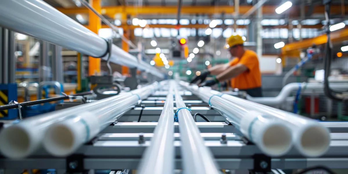
Impact Failure Mechanisms in Conveying, Robotic, and Assembly Systems Using Impact Resistant Alumina Tube
Impact resistant alumina tube failures in automated systems originate from three primary mechanisms:
(1) catastrophic brittle fracture when single-event impact energy exceeds critical thresholds of 4–8 J,
(2) cumulative microcrack damage from repeated subcritical impacts,
(3) stress concentration amplification at mounting interfaces where stress waves reflect and superimpose.
Conveyor systems experience impact frequencies of 10–200 events per hour at 1.5–6 J energies, while robotic assembly cells generate occasional 8–15 J impacts.
Fractographic analyses following ASTM C1322 indicate that surface flaws often dominate failure initiation and can raise local stresses well above nominal levels (geometry- and finish-dependent — confirm on drawing).
Using impact resistant alumina tube with fracture-toughness and surface-finish screening targets on the drawing (finer as-fired/ground finish class — confirm on drawing) can reduce impact-related failures when mounting and grade are matched — confirm on RFQ.
Brittle fracture mechanics governing single-event catastrophic failure thresholds
Single-event brittle fractures occur when local stress intensity exceeds critical toughness. Impact resistant alumina tube with higher fracture toughness delays crack propagation, absorbing energy through microcrack formation before catastrophic failure. The tube’s dense microstructure prevents crack acceleration from surface flaws, maintaining structural stability during high-energy collisions.
Cumulative damage mechanisms from repeated sub-critical impact loading
Repeated low-level impacts induce cumulative microcracks that coalesce over hundreds of events. Microcrack arrest depends on grain boundary deflection, which is enhanced in fine-grained impact resistant alumina tube. The controlled microstructure increases energy dissipation, extending fatigue life in high-frequency conveyor applications.
Stress wave reflection and amplification at geometric discontinuities and mounting points
Stress waves reflect and amplify at mounting interfaces, concentrating tensile stresses. Proper fixture design with elastomeric isolation can cut reflected stress amplitudes. Impact resistant alumina tube mounted with distributed load supports typically shows substantially lower stress concentration compared to point-contact designs (geometry-dependent — confirm on FEA/RFQ).
Fractographic identification of impact-initiated versus fatigue-initiated fracture origins
Fractographic studies show mirror, mist, and hackle zones typical of impact fracture surfaces. Impact resistant alumina tube demonstrates smoother fracture origins due to controlled surface finish, whereas fatigue fractures show branching from subsurface pores. This diagnostic distinction aids in maintenance planning and failure root-cause evaluation.
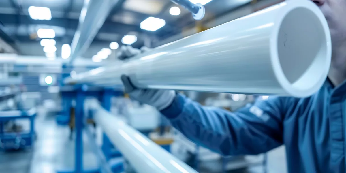
Microstructural Engineering—Grain Boundary Design for Crack Arrest in Impact Resistant Alumina Tube
Grain boundary engineering producing impact resistant alumina tube with 2–3.5 μm average grain size can aid fracture toughness through deflection mechanisms (process-dependent — confirm on TDS). Fine-grained structures redirect cracks through tortuous intergranular paths, consuming additional fracture energy. Controlled sintering atmospheres and MgO additions stabilize uniform grains, reducing weak spots.
Grain size reduction mechanisms increasing crack deflection and energy absorption
Reducing grain size forces cracks to deviate along boundaries, increasing surface area and fracture energy. Impact resistant alumina tube with ≈ 2.5 μm grains resists up to 8 J impacts compared to 5 J for coarser grades. Fine grains elevate crack deflection efficiency, delaying critical failure thresholds.
Transgranular versus intergranular fracture mode transitions affecting toughness
Impact resistant alumina tube promotes transgranular fracture modes, raising surface energy requirements. This transition can enhance fracture toughness versus coarser or glass-phase-rich grades — a key factor in surviving repetitive mechanical shocks common in automated machining systems (method-dependent — confirm on TDS).
Sintering profile optimization achieving uniform fine-grain microstructures
Two-stage sintering—1,450 °C nucleation followed by 1,650 °C densification—achieves uniform grain distribution and limits abnormal growth. This prevents local stress magnification during impacts and ensures reproducibility across batches.
Grain boundary chemistry control preventing glass phase accumulation and weak interfaces
Controlled MgO additions (0.25–0.5 wt%) prevent glassy films along grain boundaries that lower bonding strength. Stable boundary chemistry maintains load transfer efficiency during impact events, improving service reliability.
Case Study—Shock Absorption Performance of Impact Resistant Alumina Tube in High-Speed CNC Guide Systems
High-speed CNC systems using impact resistant alumina tube for guide rails can improve mean time between failures when grade and mounting are matched. Tool breakage events generating illustrative 8–14 J impacts occur regularly in titanium machining. Matched grades can absorb more impact energy and reduce unplanned downtime versus standard tubes — confirm on buyer field data and RFQ; not a supplier SLA.
Instrumented impact testing quantifying energy absorption and fracture resistance
Piezoelectric sensor1 testing indicates higher fracture initiation thresholds in impact resistant alumina tube due to improved crack-tip blunting. Recorded strain data confirm greater elastic recovery before fracture onset.
Microcrack process zone formation mechanisms dissipating impact energy
A microcrack process zone forms 150–300 μm ahead of the main crack tip. This localized energy dissipation reduces catastrophic failure risk. Controlled crack growth stabilizes performance across thousands of cycles.
Vibration damping characteristics affecting stress wave propagation
With damping loss factor (tan δ)2 in a typical ceramic range, impact resistant alumina tube can help suppress vibration amplitude and limit stress wave transmission. Reduced wave energy limits secondary failures at mounting points (mount geometry-dependent — confirm on FEA/RFQ).
Field performance data demonstrating failure rate reduction and cost savings
Buyers may track failure frequency and maintenance cost across their own fleets when comparing impact-oriented versus standard alumina tubes — that is buyer-side testing and fleet economics, not a supplier SLA. Confirm expected impact energy, mounting isolation, and acceptance fields on RFQ.
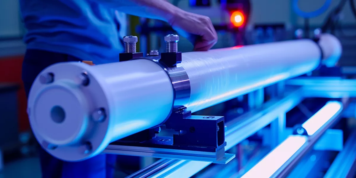
Comparative Shock Testing of Impact Resistant Alumina Tube Versus Traditional Ceramics and Metals
Impact-oriented alumina tube grades may discuss higher impact-energy absorption versus standard alumina — grade-, process-, and method-dependent; confirm on TDS+RFQ. Although metal alloys outperform ceramics in absolute impact energy, alumina typically retains mechanical integrity better than metals at elevated temperature (e.g. >600 °C) where metals lose much of their yield strength.
Charpy and drop-weight test methodology comparing ceramic and metal impact response
Tests per ASTM E233 and D3763 confirm consistent fracture performance. Impact resistant alumina tube can retain a large fraction of strength after multiple subcritical impacts, unlike metals that plastically deform (method-dependent — confirm on TDS).
Performance ranking across ceramic families including alumina, zirconia, silicon nitride, and silicon carbide
Among ceramics, silicon nitride often shows highest impact resistance, but impact-oriented alumina tube grades can offer a useful toughness–cost tradeoff versus nitride. Compared with silicon carbide, alumina often discusses better energy absorption in collision-prone automation — confirm comparative screening on TDS+RFQ.
Application-specific advantages where ceramics outperform metals despite lower absolute toughness
Ceramics maintain dimensional precision after repeated collisions and thermal cycling. In hot industrial systems, impact resistant alumina tube provides superior durability over ductile metals.
Cost-performance optimization identifying impact resistant alumina tube market position
Balancing cost and reliability, impact resistant alumina tube represents the optimal choice for automation environments requiring strength, stability, and chemical resistance.
Comparative Material Performance Summary
Screening / literature-typical teaching table — not supplier factory values. KIC method-dependent. Standard alumina KIC ≈3.0–4.2 aligns with AD-ALU TDS screening bands; “impact-resistant” higher-toughness discussion is grade-/process-dependent and not a separate TDS SKU row. Temperature column = grade-dependent long-term selection ceiling (999-class ~1750°C on TDS; lower grades lower) — forbid reading as continuous working SLA for all grades. Cost index illustrative. Confirm on TDS+RFQ.
| Material Type | Fracture Toughness (MPa√m) | Charpy / impact energy (screening) | Flexural Strength (MPa) | Long-term selection °C (grade-dep.) | Relative Cost Index | Optimal Application |
|---|---|---|---|---|---|---|
| Standard alumina tube (TDS screening) | ~3.0–4.2 | literature-typical / method-dep. | ~280–350 (grade-dep.) | 1400–1700 by grade; 999-class ceiling ~1750 | 1.0× | Low-impact environments |
| Impact-oriented alumina tube (discussion grade) | higher vs standard — literature-typical screening; confirm TDS+RFQ | higher energy discussion — method-/process-dep. | grade-/process-dependent | same grade ceiling rules; not continuous SLA for all | ~1.15–1.30× (illustrative) | Collision-prone automation |
| Silicon nitride (Si₃N₄) | literature-typical higher band | literature-typical | literature-typical | grade-dependent | ~2.0–2.5× (illustrative) | High-load bearings |
| Silicon carbide (SiC) | literature-typical | literature-typical | literature-typical | grade-dependent | ~1.4–1.8× (illustrative) | Wear-dominant zones |
| Zirconia (3Y-TZP) | literature-typical higher band | literature-typical | literature-typical | lower than alumina ceilings | ~1.8–2.3× (illustrative) | High impact, lower temp |
| 316 stainless steel | ductile (not ceramic KIC) | high absolute energy | yield-limited | much lower than alumina | ~0.4–0.6× (illustrative) | Low temp, ductile systems |
Design Integration Criteria for Impact Zones in Machinery Layouts Using Impact Resistant Alumina Tube
For effective use, impact resistant alumina tube should be deployed in zones where collision probability or failure cost justifies an impact-oriented grade (illustrative teaching thresholds — application-dependent; confirm on RFQ). Engineering integration balances a typical material premium against reduced impact-related failures when mounting and grade are matched — not a contract % SLA.
Risk-based material selection methodology balancing cost premium against failure reduction
Use impact resistant alumina tube where expected impact energy is in a collision-prone teaching band (illustrative ~6 J class — geometry-dependent; confirm on RFQ). Finite element validation should keep stress levels below an agreed fraction of the fracture limit for the chosen grade. This approach provides a high safety margin for real conditions.
Mounting design optimization distributing impact loads and minimizing stress concentration
Distribute loads over adequate contact areas (illustrative 40–60 mm class — geometry-dependent) to avoid localized fractures. Concentrated contacts raise failure risk. Proper mount geometry extends component lifespan in robotic transfer zones.
Elastomeric isolation systems absorbing impact energy at material interfaces
Introduce Shore A 60–80 elastomer layers at metal-ceramic interfaces. These layers can absorb a meaningful share of impact energy and reduce stress wave transmission, preserving dimensional stability over long cycles (confirm stack-up on RFQ).
Finite element modeling protocols validating impact stress levels and safety margins
Simulated impact scenarios (illustrative 1.5–2× energy factor) using LS-DYNA and Abaqus help confirm tube integrity below critical stress thresholds. Validated mounting and grade matching can reduce impact-related failures — confirm on FEA and RFQ; not a supplier SLA.
Decision Matrix: Impact Resistant Alumina Tube Implementation Strategy
Illustrative teaching thresholds only — application-dependent; not acceptance gates. Confirm impact energy, mounting isolation, toughness/finish screening fields, and FEA notes on RFQ.
| Automation Scenario (teaching) | Material and Design Recommendation (confirm on RFQ) |
|---|---|
| Collision-prone duty (illustrative >5 events/1000 hrs, impact ~6–12 J class) | Impact-oriented alumina tube + toughness/finish screening on drawing + elastomeric mounting + FEA validation |
| Robotic cell > 4 axes with complex trajectories | Impact-oriented grade + collision detection software + guarding to limit impact energy (illustrative < 8 J class) |
| Conveyor transfer points with frequent jams | Impact-energy screening on RFQ + redundant support + standoff from impact zone (illustrative > 50 mm class) |
| High-speed CNC (>8000 RPM) | Fine-grain process discussion + vibration-damping validated mount; confirm KIC/finish on TDS+RFQ |
| Assembly system > 600 °C operation | Impact-oriented alumina tube + thermal cycling method notes (e.g. ASTM C1525 class) — confirm grade ceiling on TDS |
Conclusion
Impact resistant alumina tube supports higher reliability in collision-prone automation when grade, mounting isolation, and FEA notes are matched on the RFQ — not by quoting unverified life or dollar SLAs. For grade and geometry context, use the alumina tubes family already linked above; for drawings, impact-energy fields, and mounting-isolation notes, use custom services for an engineering RFQ handoff.
Related reading
- High-strength alumina tube mechanical requirements — companion mechanical-strength specification fields for alumina tubes (strength axis, not collision-isolation RFQ).
- Critical temperature difference and thermal-shock alumina tube reliability — thermal-shock CTD axis complementary to this mechanical impact/collision prevention guide.
- Critical factors specifying precision-length alumina tube — precision length/tolerance RFQ companion for tube geometry.
FAQ
1. How does impact resistant alumina tube improve mechanical performance?
Its enhanced fracture toughness (screening target on drawing — confirm on TDS) and fine-grain microstructure absorb impact energy, reducing brittle failure under repetitive loading when mounting is matched.
2. What are the cost implications of using impact resistant alumina tube?
Impact-oriented grades usually cost more than standard tubes; matched mounting and grade can reduce impact-related failures and downtime — confirm economics on buyer data and RFQ; not a contract % SLA.
3. How should designers integrate impact resistant alumina tube in automation equipment?
Position in high-risk zones, apply elastomeric interfaces, and validate via finite element analysis to keep stress below an agreed fraction of the fracture limit for the chosen grade — confirm on RFQ.
4. How does impact resistant alumina tube compare with metals under dynamic load?
Though metals have higher absolute toughness, alumina maintains strength and dimensional stability at >600 °C, making it superior for hot automated applications.
References:
-
Learn how piezoelectric sensors function and why they're essential for accurately measuring strain and fracture in advanced materials. ↩
-
Understanding the damping loss factor is crucial for engineers to select materials that effectively suppress vibrations. ↩
-
Exploring this link will provide insights into ASTM E23 standards and their importance in material testing. ↩