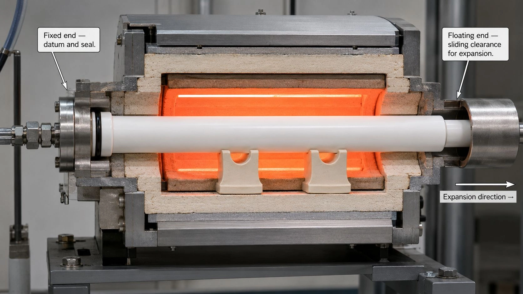
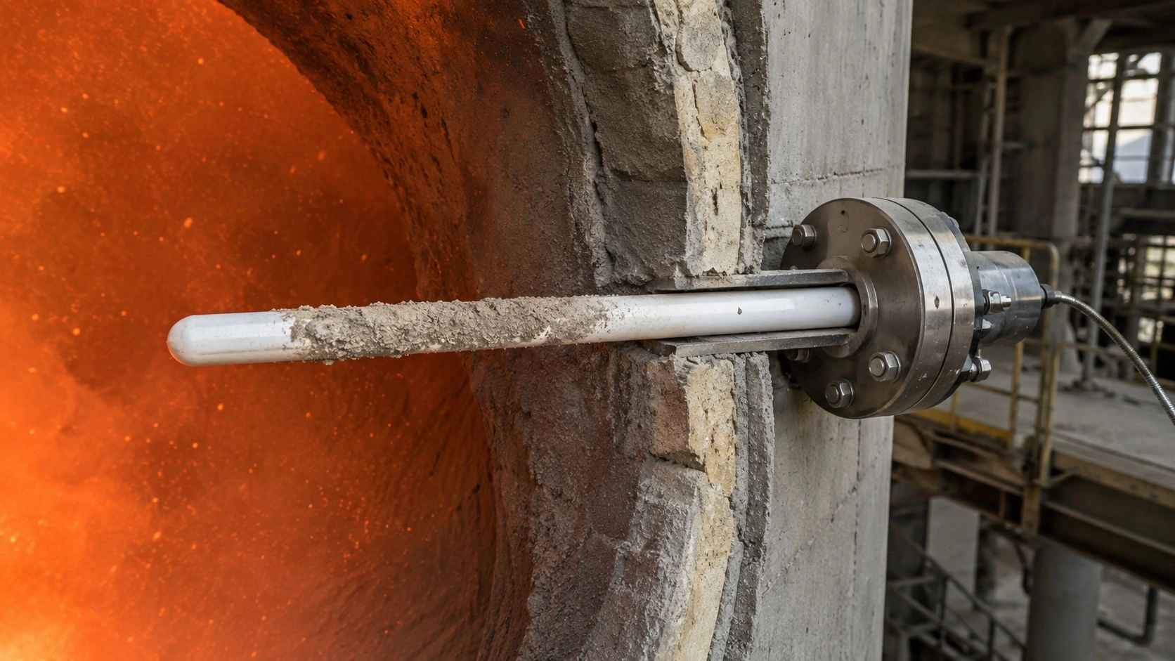
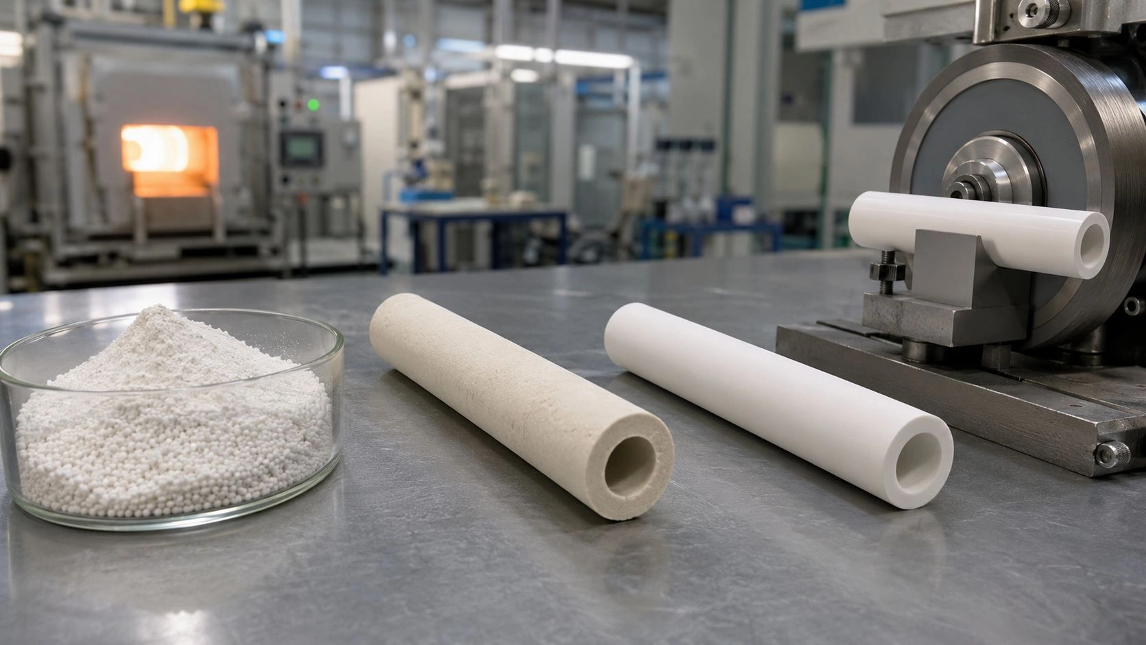
Square Alumina Tube Spec for Corona Electrodes: Voltage, Wall, Corner Radius, RFQ
An engineering specification brief for equipment and electrical-insulation engineers — how to lock voltage and dielectric path, wall thickness and corner radius, surface finish and electrode fit, failure-mode checks, and a complete RFQ for square alumina tubes in corona electrode and ozone-generator assemblies.
Specify a square alumina ceramic tube for corona electrode service by defining the electrical stress first, then the tube geometry. The RFQ should include voltage and frequency, discharge gap, electrode position, required dielectric path, outside and inside square dimensions, wall thickness, corner radius, length, straightness, surface finish, alumina purity grade on the drawing, density or porosity, end treatment, cleaning requirement, and dielectric-strength verification. The tube should be designed to prevent dielectric breakdown through the wall, surface tracking along contaminated or rough faces, edge arcing at sharp corners, and mechanical cracking during assembly.
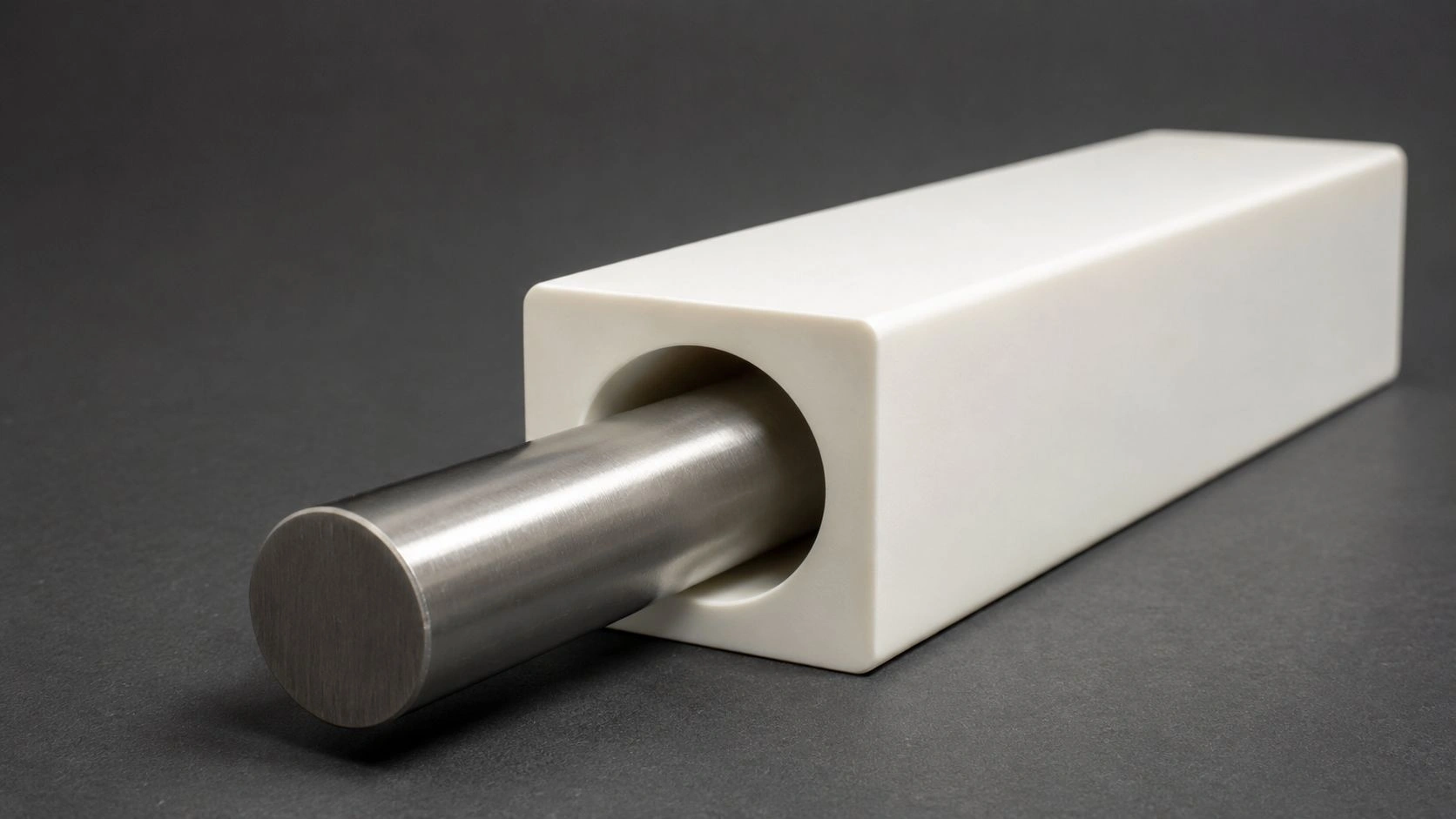
A square alumina ceramic tube functions as both a dielectric barrier and a positioning body around the metal conductor, so bore fit, wall balance, corner radius, and surface condition should be specified before production.
Define the Corona Electrode Function Before the Tube Dimensions
A square alumina ceramic tube in a corona electrode assembly is not only a mechanical sleeve — it is a component of the electrical field geometry. Specifying only the outer and inner dimensions without first defining the electrode function produces an RFQ that a supplier cannot complete correctly.
In ozone generation and dielectric-barrier-discharge assemblies, a ceramic dielectric serves two distinct functions: it separates electrodes to prevent direct arc formation, and it distributes discharge across the active gas region as many surface microdischarges instead of a single concentrated arc path. Sources on ceramic ozone generator construction confirm that the ceramic tube acts as a barrier, blocking direct discharge between electrodes and promoting distributed microdischarges across the active ceramic face. The electric field behavior at the ceramic surface, through the ceramic wall, and at the air-gap interface is therefore part of what the tube specification must address.
Before writing outer square dimensions or wall thickness, the design team should define:
- Applied voltage (RMS and peak), waveform, and frequency
- Electrode shape and how it contacts or sits against the alumina tube
- Discharge gap — the air or gas space between the ceramic and the counter-electrode
- Gas type and ozone concentration if the environment contains reactive gases
- Cooling method, if any, and operating temperature
- Whether the square profile is required for anti-rotation, fixed electrode spacing, optical alignment, or packing density in a multi-tube cell
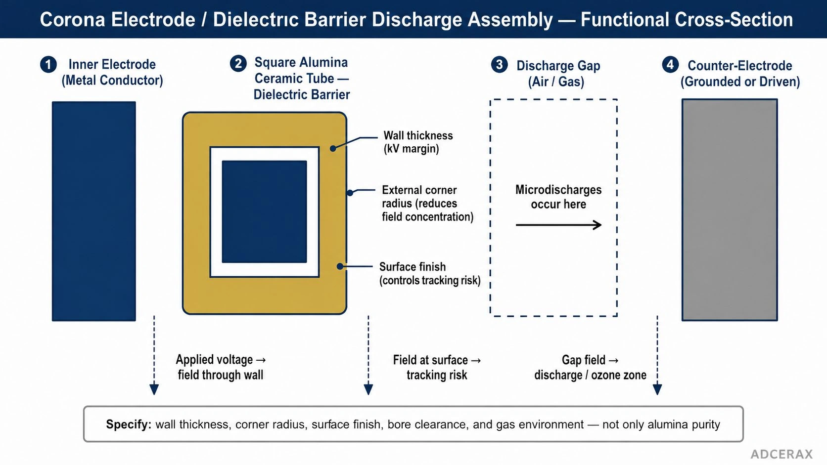
In a corona or dielectric-barrier-discharge assembly, the square alumina ceramic tube is part of the electrical field path, so voltage, discharge gap, wall thickness, surface finish, and electrode position should be reviewed together.
The square geometry provides fixed orientation in a matching electrode housing, which is particularly useful when the electrode position relative to the discharge gap must be maintained consistently across multiple tube positions in a cell array. If the electrode function does not require fixed orientation, round tubes may also be appropriate — but if orientation, flat-face mounting, or anti-rotation matters, the square section is the functionally justified choice.
Specify Electrical Stress, Dielectric Path, and Safety Margin
After the electrode function is defined, the electrical specifications can be translated into tube geometry — primarily wall thickness, dielectric path length, and surface requirements.
The core electrical parameters to specify are: operating voltage (RMS and peak), waveform shape, frequency, expected overvoltage during operation, discharge gap dimensions, dielectric wall thickness in each of the four flat sections, and the intended creepage path along any exposed surface.
Wall thickness is not simply voltage divided by a dielectric strength number. Dielectric strength calculated as coupon breakdown voltage divided by specimen thickness is a specimen result — geometry, surface, gap, and gas dominate installed corona duty. ASTM D149 or IEC 60243 (or another agreed method), with test conditions stated, can support screening of solid insulating materials under commercial-frequency conditions; failure criteria, electrode size, specimen thickness, and procedure can significantly affect results. A dielectric strength value from a supplier data sheet, typically measured on a small flat disc under controlled laboratory conditions, cannot be applied directly to a square tube installed in an electrode assembly with corners, partial-surface contact, deposited films, humidity, and ozone.
The practical approach is to use the material dielectric strength value as a screening criterion and to keep wall and creepage such that operating stress stays well below coupon-nominal strength — margin is duty-specific. For high-voltage corona service, also specify the factors that affect surface discharge: surface roughness, cleaning state, corner radius, and electrode clearance. Do not treat a datasheet kV/mm as an installed corona design allowable.
State the alumina purity grade on the drawing or RFQ (for example 95 / 99.00 / 99.50 / 99.70 / 99.90 Al₂O₃). IEC 60672-3 composition-class screening (C795/C799) is a useful comparison framework for electrical-insulation ceramics — it is not a finished corona-tube certificate by itself. Align grade choice to insulation, chemical resistance, and manufacturability before the tube drawing is finalized.
The following table maps each electrical specification to the threshold evidence and decision direction.
| Criterion | Specification Anchor | Decision Direction |
|---|---|---|
| Operating voltage | Specify RMS, peak, waveform, frequency, and duty cycle | Sets minimum dielectric path and safety margin requirement |
| Discharge gap | Define electrode-to-dielectric and dielectric-to-counter-electrode distances | Controls discharge uniformity and arcing risk at gap edges |
| Wall thickness | Specify all four flat sides independently | Prevents local thin-wall stress concentration at asymmetric sections |
| Dielectric data | Request ASTM D149 or IEC 60243 (or agreed method) breakdown data with conditions stated | Supports screening, not absolute installed survival guarantee |
| Surface finish | Define inner and outer Ra or surface quality | Controls tracking, discharge stability, and deposit behavior |
| Creepage path | Define distance along exposed surface between electrodes | Prevents surface tracking at low-field conditions |
| Corner radius | Specify internal and external radii on all four corners | Reduces field concentration and machining crack risk |
| Alumina grade | Specify purity (drawing/RFQ grade) and density / porosity | Aligns insulation, chemical resistance, and manufacturability |
Values indicative; verify per ASTM D149 or IEC 60243, ASTM C373 or agreed method, IEC 60672-3 screening class, and supplier-specific ceramic data — none of these alone is a finished-goods corona-tube certificate.
Define Square Tube Geometry, Corner Radius, Bore Fit, and Surface Finish
Square alumina tubes require more complete geometry specification than round stock tubes. Corners, bore position, wall balance, and surface finish all affect assembly, electrode alignment, and electric-field behavior.
Drawing required fields for square alumina ceramic tubes:
- Outer square dimension — side length, with tolerance; specify whether all four sides must be equal or whether asymmetry is acceptable
- Inner bore or inner square dimension — side length and tolerance; for a circular bore inside a square outer section, specify bore diameter and bore position relative to the outer reference face
- Wall thickness on each of the four sides — separately, not as a nominal average; wall-thickness variation can create local high-field zones
- External corner radius — the radius on all four exterior longitudinal edges; sharp external corners concentrate electric field and are also more likely to chip during handling or machining
- Internal corner radius — the radius on the four interior bore corners if the bore is square; these also affect field behavior and machining integrity
- Length and length tolerance
- Straightness — maximum bow over the full tube length
- Twist — maximum angular deviation of the face orientation from end to end
- End-face squareness and chamfer — for electrode lead-in, seating, or end-face contact
- Surface finish — Ra or equivalent for the inner bore surface and outer faces; specify separately where electrode contact, gas flow, or discharge uniformity matters
- Cleaning and handling state — whether surfaces must be solvent-cleaned, ultrasonic-cleaned, or kept contamination-free before use
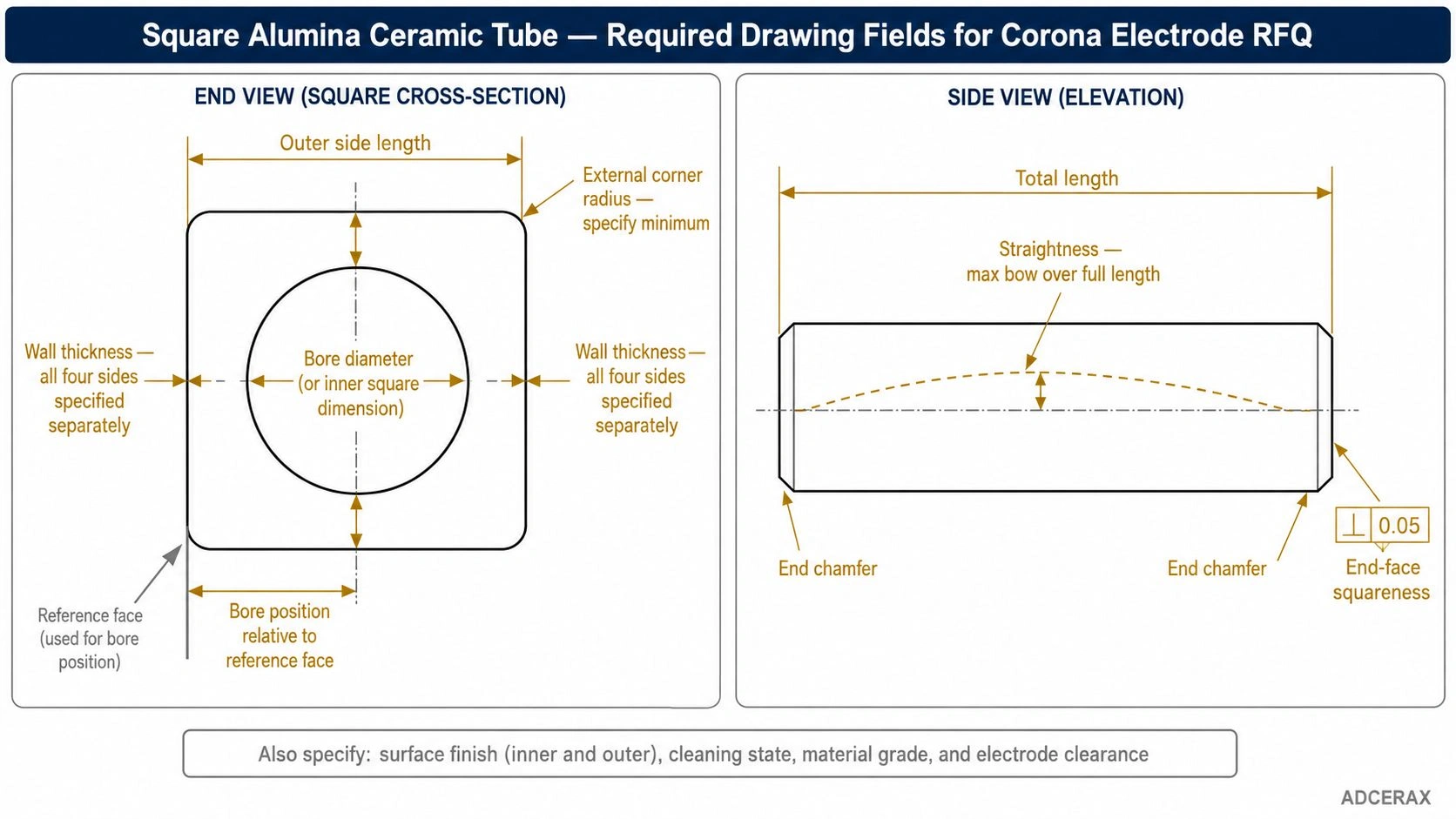
A complete RFQ drawing should define outer size, bore position, wall thickness, corner radius, length, straightness, chamfer, end-face squareness, and surface requirements.
Corner radius is a critical design control, not a cosmetic note. A sharp external corner on a square alumina tube can concentrate the electric field at that edge, reducing the local dielectric margin below the bulk material value. The same corner is also a preferred initiation site for machining cracks, particularly if tight tolerance grinding is applied without controlled infeed. The RFQ should always specify the minimum acceptable external corner radius and confirm with the supplier that this radius is achievable in both as-fired and ground surfaces.
Electrode fit and bore clearance — the clearance between the inside bore of the alumina tube and the outside of the electrode conductor — must be specified for both mechanical and electrical reasons. A bore that is too tight creates contact stress, can damage an electrode coating, and makes insertion difficult. A bore that is too loose allows the electrode to shift, creating an asymmetric discharge gap that affects treatment uniformity or ozone output.
Do Not Misdiagnose Breakdown, Tracking, Edge Arcing, and Mechanical Cracking
A failed square alumina tube in a corona electrode assembly may have failed for several different reasons, and each requires a different corrective specification. Treating all failures as insufficient material purity or wall thickness misses the most common actual causes.
The most common failure misdiagnosis is replacing a tube with a higher-purity or thicker version of the same design, without addressing the geometric or surface condition that actually caused the failure. Purity and thickness are one variable each; the failure mechanism may be controlled by the corner radius, surface cleanliness, electrode fit, gas exposure, or end treatment — none of which improve when only purity is upgraded.
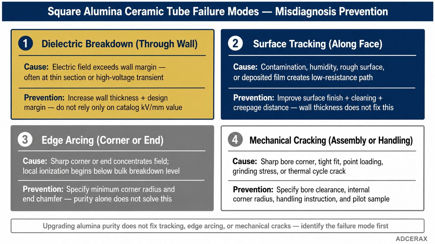
Dielectric breakdown, surface tracking, edge arcing, and mechanical cracking require different corrective specifications, so the failure mode should be identified before changing material grade or wall thickness.
Dielectric breakdown through the wall occurs when the electric field through the ceramic exceeds the material's withstand capability under the actual assembly and service conditions. Research on alumina dielectric strength testing confirms that measured values depend strongly on test procedure, electrode size, voltage ramp rate, electrode conditioning, and sample thickness — making values from different suppliers or standard tables difficult to compare directly without knowing the test conditions. A breakdown failure indicates the wall thickness, dielectric margin, or material grade under the actual field conditions was insufficient.
Surface tracking along the tube face occurs when a contaminated, humid, rough, deposited, or damaged surface path between electrodes develops enough conductivity to sustain a current without bulk breakdown. Tracking damage typically leaves a discolored or carbonized line along the surface. The corrective specification is surface finish, cleaning, creepage distance, and coating — not primarily wall thickness or purity.
Edge arcing at corners or electrode ends occurs when field concentration at a sharp corner, exposed electrode edge, or misaligned gap allows ionization to begin at a lower voltage than the bulk ceramic breakdown level. The preventive specification is corner radius, chamfer, end geometry, and electrode clearance.
Ozone and plasma exposure effects — rough surfaces from ozone or reactive gas erosion, deposited films from gas-phase reactions, or contamination from electrode materials — change the surface discharge path over time. These are application-specific degradation mechanisms that should be addressed by specifying surface finish, cleaning intervals, gas/ozone exposure on the RFQ, and inspection intervals — not by publishing a locked ozone-grade SKU list.
Mechanical cracking from tight electrode insertion, point loading during assembly, sharp bore corners, insufficient chamfer, or handling damage creates a different failure pattern. Machining cracks often initiate at sharp transitions, grinding stress concentrations, or bore corners in square-bore alumina tubes. The preventive specification is bore tolerance, internal corner radius, chamfer, and handling instructions.
RFQ Checklist for Square Alumina Tubes in Corona Electrode Assemblies
The following checklist converts the electrical, geometric, and failure-prevention requirements into a complete supplier-verifiable RFQ package.
Electrode function and electrical environment:
- Electrode role — dielectric barrier, insulating holder, anti-rotation guide, spacer, or combination
- Operating voltage — RMS and peak
- Waveform and frequency
- Expected overvoltage condition
- Gas type — air, oxygen, dry gas, ozone concentration if known
- Humidity exposure during operation
- Cooling method and operating temperature range
Tube geometry (all required on drawing):
- Outer square dimension with tolerance
- Inner bore dimension (round or square) with bore position tolerance
- Wall thickness on each side separately
- External corner radius (minimum)
- Internal corner radius if bore is square
- Total length with tolerance
- Straightness — maximum bow over full length
- Twist — maximum angular deviation end-to-end
- End chamfer and end-face squareness
- Electrode clearance — nominal and acceptable range
Material and surface:
- Alumina purity grade on drawing/RFQ — 95 / 99.00 / 99.50 / 99.70 / 99.90 (or drawing-specified)
- Density and apparent porosity — per ASTM C373 or agreed method aligned to drawing/PO
- Flexural strength data if the tube is load-bearing or clamped — per ASTM C1161
- Surface finish — inner bore Ra and outer face Ra
- Cleaning state required on delivery
Verification and documentation:
- Dielectric breakdown data request — ASTM D149 or IEC 60243 (or agreed method), with test conditions stated
- Dimensional inspection report covering CTQ features
- Material certificate with grade, density, and porosity
- Pilot sample approval before repeat production release
- Packing specification — protection for corners and tube ends during transport
Ask the supplier to confirm manufacturability, recommend any radius or tolerance adjustments required for the square section, and identify which dimensions can be held in as-fired form versus which require grinding or additional processing.
For square/corona tube stock and custom electrode-tube fabrication, route RFQs through square alumina tubes and custom ceramic manufacturing. Complementary engineering checklists: custom ceramic electrode tube RFQ fields (full RFQ information list) and alumina purity options for ceramic electrode tubes (purity-axis selection).
Specifying square alumina ceramic tubes for a corona electrode assembly? Send the electrode drawing or concept sketch, operating voltage and waveform/frequency, discharge gap, gas/ozone exposure, required tube geometry including wall thickness and corner radius, surface finish, and inspection plan. A manufacturability review against those RFQ fields can be returned before any order commitment.
Related reading
- Square vs round alumina ceramic tubes for electrode assemblies — When the first decision is square vs round electrode tube geometry — before locking wall thickness and corner radius on the drawing.
- Square alumina tube dielectric strength testing for corona use — When to request dielectric strength data for corona-service square alumina tubes — and why a datasheet kV/mm is not an installed guarantee.
- Long square alumina ceramic electrode tubes — straightness and handling — Straightness and handling risks on long square alumina electrode tubes — a length-axis control, not the voltage-to-wall translation.
Frequently Asked Questions
Why use square alumina ceramic tubes for corona electrode applications?
Square alumina ceramic tubes provide electrical insulation, fixed electrode orientation, anti-rotation positioning, stable spacing, and surfaces suitable for ozone-bearing duty when gas exposure is stated on the RFQ. The square profile is particularly useful in multi-tube electrode arrays where consistent tube orientation and electrode position must be maintained across each cell position. Alumina offers high dielectric strength, low porosity, chemical stability in ozone environments, and purity grades that can be matched to the electrode design requirements.
How does dielectric strength relate to wall thickness for alumina tube specification?
Dielectric strength expressed in kV/mm is a test-coupon result obtained under controlled laboratory conditions. For a square alumina tube in a corona electrode assembly, the wall thickness should be chosen so operating stress stays well below coupon-nominal strength — margin is duty-specific — while also accounting for corner field concentration, surface contamination, discharge exposure, and the fact that the installed assembly differs from the test specimen. ASTM D149 or IEC 60243 (or agreed method) can define the breakdown test, but the result should support the design, not replace it, and is not an installed corona design allowable.
What is the correct corner radius for a square alumina corona electrode tube?
The correct external corner radius should be sufficient to reduce field concentration at the edges and to prevent chipping during handling and machining. The minimum acceptable radius depends on the tube size, wall thickness, applied voltage, and machining method. The RFQ should specify a minimum radius and ask the supplier to confirm achievability for both as-fired and ground surfaces.
What causes surface tracking failure in square alumina electrode tubes?
Surface tracking occurs when a low-resistance path develops along a contaminated, rough, humid, or deposited surface between electrodes. It is not a bulk dielectric failure — it is a surface-condition failure. The preventive specification includes surface roughness requirements, cleaning state, creepage distance, and whether a sealed or glazed surface is required.
What should the inspection plan include for square alumina corona electrode tubes?
The inspection plan should include: dimensional inspection of all CTQ features (outer and inner dimensions, wall thickness, corner radius, bore position, length, and straightness), visual inspection of corner condition and end faces, density and porosity (or water absorption) per ASTM C373 or agreed method, dielectric breakdown data per ASTM D149 or IEC 60243 (or agreed method), and a pilot sample assembly fit check. For production batches, specify sampling method, lot traceability, and material certificate with each shipment.