Alumina furnace tubes longer than about 1 m need designed axial expansion clearance. Fix or locate one end for alignment and sealing; allow the opposite end to float, slide, or expand through a compliant seal. Rigid clamping at both ends is a common root cause of end cracks and ring cracks—often misread as “bad alumina.” Geometry and constraint come first; grade selection follows. For reviewable OD/ID/wall/length ranges and ADCERAX grade options that support long-tube RFQs, start from the furnace alumina tube specifications for long-tube review.
This article is for furnace and thermal-process engineers and buyers who must decide when a dedicated floating end (or expansion joint) is required, how sliding supports should behave, and which OD / wall / length / support / seal fields belong on the RFQ. It is not a sizes catalog, not a solar-diffusion process-position guide, and not a protection-tube or electrode-purity deep dive. Keep the money-page head terms for the product catalog; this page owns the >1 m expansion-joint / floating-end / OD–wall–length RFQ intent.
3-Minute Decision: Expansion Joint vs Longer Monolithic Tube
- Total length > ~1 m, long hot zone, or large ΔT → design a floating end + sliding supports. One fixed datum end; axial clearance at the free end; supports that do not lock the tube axially.
- Short tubes (≪1 m) with soft seals that can absorb movement → a dedicated expansion joint is often unnecessary. Still avoid hard two-end clamp-up if thermal cycling is severe.
- Very long spans or steep axial gradients → evaluate segmentation, closer sliding supports, or thicker wall—qualitatively with the furnace layout. Do not invent service-life numbers from a blog calculator.
- Default composition screen for general furnace long tubes → 99.5% alumina. Cleanliness-sensitive duty → step up to 99.7% or higher-purity alumina. Structural supports away from the contamination path may use lower-purity alumina when duty and load allow.
- Expansion mechanics first, SKU second. Changing purity will not fix a tube locked at both ends.
Why >1 m Needs Designed Clearance
Low thermal expansion is not zero expansion. Over short thermocouple wells, soft seals often absorb movement. Over multi-meter process or work tubes, axial growth, end-seal compression, support friction, and hot-zone gradients stack into real constraint stress. Alumina does not yield plastically—restrained expansion becomes cracking stress at the weakest constraint or contact. That is why length, hot-zone length, and end conditions belong on the same drawing review as purity.
Qualitative CTE note (alumina grades, mean CTE 25–800 °C): 99.9% / 99.7% / 99.5% / 95% alumina = 7.6 ×10⁻⁶/K; 99% alumina = 7.2 ×10⁻⁶/K. These figures support composition comparison only. Do not treat this page as a clearance calculator: design floating-end clearance from the drawing ΔT, the actual hot-zone length, and the applicable supplier TDS—not from a blog mm prediction table. Mean CTE published for 25–800 °C must not be extrapolated into a hard 20–1000 °C engineering table on this page. If your cycle exceeds the TDS temperature window used for mean CTE, require a grade-specific thermal-fit from the supplier drawing package rather than scaling a blog estimate.
Cold fit ≠ hot fit. A tube that slides freely at room temperature can lock at temperature if seals swell, deposits bridge the gap, or cold clearance never accounted for hot growth. Installers who set metal caps “snug” at ambient often discover the free end has zero travel once the hot zone is at temperature.
Gradients matter more than uniform heat. A central hot zone pushing against cooler extensions creates differential strain at zone boundaries—often more damaging than total length alone. Ramp rate and soak profile change how fast that gradient forms; a fast ramp into a long tube with rigid ends is a classic crack setup even when the peak temperature is within the grade’s selection ceiling. Within broader industrial furnace ceramics practice, long brittle tubes are treated as constrained thermal systems, not as drop-in metal pipe.
Fix One End, Float the Other
The practical rule for long alumina furnace tubes: fix one end as the datum for alignment and primary sealing; let the opposite end move axially.
| End / interface | Intent | Typical approach | Failure if wrong |
|---|---|---|---|
| Fixed end | Position datum + reliable seal | Compression fitting, fiber gasket, or locked O-ring groove that does not crush the wall | Loss of alignment or seal leak |
| Floating end | Absorb axial growth | Sliding O-ring bore, bellows, fiber-packed gland, or slip-fit cap with designed clearance | End cracks from axial lock-up |
| Two rigid seals | Avoid | Flange bolts / hard collars on both ends | Compressive stress → sudden fracture |
| Metal end hardware | Allow mismatch | Sliding fit, fiber interlayer, or spring-loaded contact—not a bonded lock | Shear at ceramic–metal interface (metals typically expand more than alumina; industry-typical steel CTE is higher—not an ADCERAX TDS value) |
Clearance at the floating end must cover the expected hot growth for your ΔT and hot-zone length, with margin for seal stack-up and deposits. Size that clearance from engineering drawings and TDS—not from a generic blog mm table. Document which end is the datum on the installation sketch so maintenance crews do not “tighten both ends” after a seal change.
Vertical and inclined tubes still need a free direction for growth, but gravity and seal weight change how the floating interface is detailed. Do not assume a horizontal O-ring gland transfers unchanged to a vertical stack without reviewing support seats and seal retention.
Support Layout for Horizontal Long Tubes
Supports complete the expansion system. A saddle that grips both sides, a tight sleeve, or an axial stop becomes a hidden fixed point and defeats the floating end. Every support is either a sliding bearing or an unintended clamp—there is little middle ground on brittle alumina.
- Allow axial slide. Smooth ceramic saddles, soft refractory cradles, or wide pads with no axial ledge. Check that fiber wraps cannot sinter into a hard collar after repeated cycles.
- Avoid point loading. Narrow V-edges and misaligned brackets concentrate bending; combined with thermal stress they produce characteristic ring cracks at the contact. Prefer contact width that spreads load along a meaningful arc of the OD.
- Account for sag and boat load. Horizontal multi-meter tubes carry gravity and internal loads; wall thickness and support spacing must be reviewed together with expansion clearance—especially for thin-wall long spans inside the KB review envelope (wall 0.5–20 mm; length up to 3500 mm subject to section and straightness review).
- Keep supports coaxial with the tube axis. Twisted or stepped brackets introduce local bending that looks like “material weakness” after the crack appears.
Where multi-material tube families share a furnace line, treat alumina long-tube expansion rules separately from other multi-material ceramic tubes; this page stays on alumina furnace-tube constraint design.
Do Not Misdiagnose Expansion Cracks as “Bad Alumina
| Signature | Likely cause | First fix |
|---|---|---|
| Crack near end / seal | Restrained axial expansion | Add floating clearance; soften seal clamp-up |
| Circumferential ring crack at support | Point load / non-sliding support | Widen contact; allow axial slide |
| Mid-span crack after rapid ramp | Gradient + constraint + shock | Review ramp, supports, and wall together |
| Chip at end face after assembly | Over-compression or impact | Chamfer/radius + controlled seal torque |
Stepping purity without fixing constraint rarely stops these failures. For short sensor wells where geometry-before-grade is the main decision (not >1 m work-tube expansion), use a separate protection-tube specification workflow rather than this expansion-joint page.
OD / Wall / Length RFQ Fields for Long-Tube Review
Send installation context with geometry. A bare “OD40 × ID32 × L1500 alumina tube” line is not enough to confirm floating clearance, support spacing, or seal design. Use the key information for quoting alumina tubes checklist and add the expansion-specific fields below.
Dimensional review ranges (page/KB review wording—not a guarantee that every OD×wall×length combination ships): OD/ID 2–120 mm; length 10–3500 mm; wall 0.5–20 mm; tolerances up to ±0.05 mm where the drawing and process allow—always “review, not blanket guarantee. Straightness across the listed alumina grades is commonly 1 mm/m against the drawing datum where applicable.
- Total length and hot-zone length
- OD / ID / wall (and open/closed ends, ports, holes)
- Orientation: horizontal / vertical / inclined
- Support span, contact material, and sliding provision
- Fixed-end location and seal type; floating-end clearance intent
- Peak / continuous temperature, ramp and cooldown, cycle count
- Atmosphere and pressure; internal boat or gas load
- Preferred alumina composition (default screen 99.5% alumina) and failure photos if replacing a cracked tube
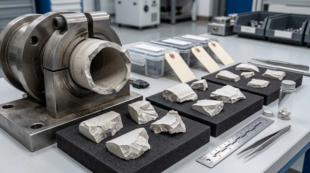
If you are replacing a cracked tube, annotate crack location on the installation sketch (distance from fixed end, nearest support, seal face). Photos plus that map usually reveal constraint issues faster than another purity step-up.
Inquiry handling is typically framed as a 24 h response window (not a 24 h quote promise); prototypes and customs follow agreed lead times after drawing review. ADCERAX will not claim drop-in universal metal-end solutions or unlimited stock of every OD×length combination—long tubes are drawing-reviewed builds.
ADCERAX Grade Map for Furnace Long Tubes
Use ADCERAX grades only. Long-term temperature values are material selection ceilings—not guaranteed service life under load, atmosphere, or gradient. A tube can sit under its ceiling and still crack if both ends are locked. IEC C795 / C799 is a composition group, not a finished-part certificate. Density, strength, and conductivity from the TDS support screening; they are not part design allowables for every wall and span.
| Al₂O₃ wt% (nom.) | IEC | Selection ceiling °C | Mean CTE 25–800 °C (×10⁻⁶/K) | Long-tube note |
|---|---|---|---|---|
| 99.90 | C799 | 1750 | 7.6 | Clean / contamination-critical step-up |
| 99.70 | C799 | 1700 | 7.6 | cleanliness step-up |
| 99.50 | C799 | 1650 | 7.6 | Default screen for general furnace long tubes |
| 99.00 | C795 | 1600 | 7.2 | Support / lower contamination-path review |
| 95 | C795 | 1400 | 7.6 | Only when duty and load allow |
For purity-driven electrode or metallization tubes outside this expansion-joint scope, use the dedicated alumina purity options for electrode tubes guide. Do not specify non-catalog labels as sellable SKUs on furnace long-tube RFQs.
Evaluating expansion-joint design for an alumina tube longer than 1 m? Share the tube drawing, total and hot-zone length, OD/ID/wall, maximum temperature and ramp profile, support layout, seal design, and fixed/float plan. ADCERAX can review whether the floating clearance, wall, support saddles, or a segmented layout needs revision—no purchase commitment required for that engineering screen.
Frequently Asked Questions
How much axial growth should I plan for on a long alumina furnace tube?
Plan clearance from your drawing T, hot-zone length, and the applicable alumina TDS mean CTE (25–800 °C: 7.6 for 99.9%/99.7%/99.5%/95% alumina; 7.2 for 99% alumina). This blog does not publish an axial mm prediction table and does not authorize 20–1000 °C blog calculators.
Should a long alumina tube be fixed at both ends?
No for tubes longer than about 1 m with significant hot-zone temperature. Locate one datum end and float the other through a sliding or compliant seal.
Where should the floating end sit?
Usually opposite the alignment or primary gas-seal datum—whichever end is easier to make compliant given gas flow, access, and supports.
Why do long tubes crack near the ends?
Most often restrained expansion, over-compressed seals, or rigid metal hardware. Soften the free end and verify cold-vs-hot clearance before changing grade.
Must supports slide as well?
Yes. A snug sleeve or axial stop acts as a second fixed point. Use wide, low-friction contacts that allow axial movement.
What belongs in a long-tube RFQ?
Total and hot-zone length, OD/ID/wall, orientation, support layout, fixed/float seal plan, temperature profile and ramps, atmosphere, internal load, preferred alumina composition, plus crack photos with the installation sketch when replacing a failed tube.