Choose a tube furnace when the process needs a defined work-tube path, potentially with controlled gas flow or a sealed configuration, and the sample fits the usable bore and heated zone. Choose a muffle furnace when chamber loading, access, or multiple containers better suits the work. Neither name guarantees an atmosphere, temperature limit, or uniform sample temperature; those depend on the specific equipment and accessories. The choice also changes the ceramic component to specify: a work tube and end interfaces for one arrangement, or sample containers and supports for the other.
Begin with sample chemistry, size, atmosphere, container, and position. Check clearance, working zone, and gas-path interfaces alongside the headline temperature.
What Is the Physical Difference Between a Tube Furnace and a Muffle Furnace?
A tube furnace heats a work-tube region. The sample may sit in a boat or holder inside the tube, or another load arrangement may be specified for the process. The tube bore sets a limit on the sample and fixture envelope. Total tube length and mounting position affect where the load sits relative to the heating elements and how far the ends project beyond the hot region. Where gas flow or a sealed process is required, the work tube is one part of the process boundary; end flanges, seals, connections, and equipment ratings complete it.
An alumina furnace tube is one possible ceramic work tube when its grade, size, geometry, and process compatibility fit the selected equipment. Its nominal diameter alone cannot establish that the seal will mate, the hot section will be supported appropriately, or the sample holder will pass through the usable bore.
A muffle furnace, often described as a chamber or box furnace in this context, places the sample in an accessible enclosed heating chamber. Samples may rest on a shelf or within crucibles, boats, or trays. Chamber dimensions and the permitted loading pattern govern how many containers fit, how they are spaced, and where they can sit during heating. A container’s outside footprint, height, lid, and clearance can matter as much as its internal sample capacity.
Work tube, bore, and end interfaces
For a horizontal tube furnace, sketch the installed tube, heated zone, support points, boat, and sample. Mark OD, ID, wall, length, and end features. Seals, flanges, gas connections, and the proposed tube must fit the complete system. The tube alone does not create a gas-tight assembly.
Chamber, shelf, and sample containers
For a muffle furnace, sketch the usable chamber and the planned arrangement of crucibles or trays. Allow for loading access and clearances specified by the equipment maker, and consider whether a lid, cover, or separate containment is necessary for the sample chemistry. A shelf or support may have its own temperature and load limits. For example, Thermo Scientific’s published muffle-furnace listing identifies chamber heating elements, a vent, a temperature-monitoring port, and an optional shelf with its own limit. Those are details of the listed model, not guaranteed features of all muffle furnaces.
The two architectures thus create different sample environments and different component interfaces. Neither physical shape alone determines the correct process.
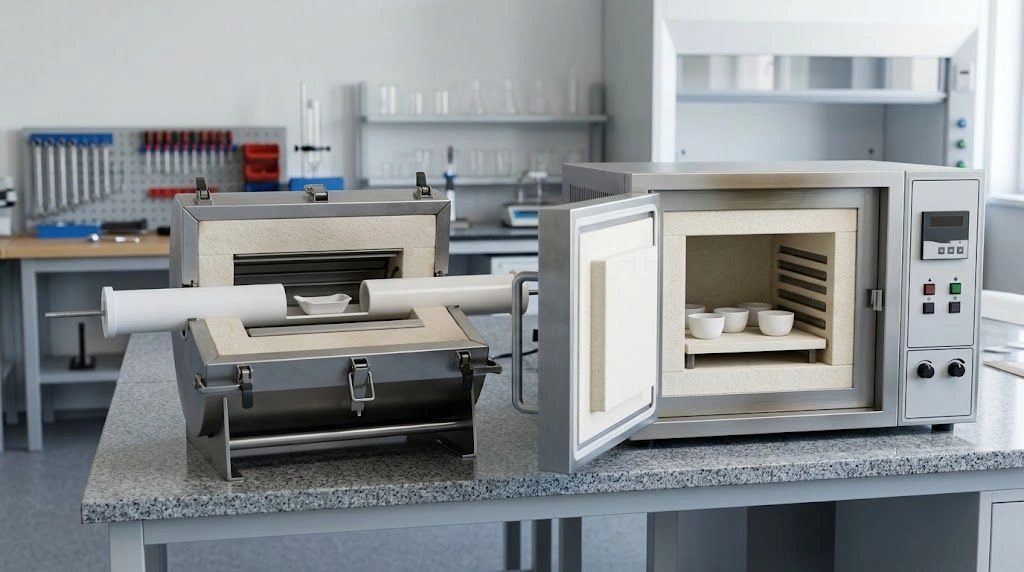
A physical equipment comparison shows the work-tube path and the accessible chamber loading space.
Which Process Conditions Determine the Choice?
Start with the sample environment rather than a catalogue maximum temperature. A practical review follows five steps:
- Define the atmosphere at the sample. State whether air is acceptable or a specified gas, gas flow, vacuum, or other verified environment is required. Include the relevant purity, flow, pressure, and exhaust conditions for equipment review.
- Draw the complete load envelope. Include the sample, boat or crucible, lid, support, and handling clearance. Compare that envelope with the usable tube bore or chamber space, not just a nominal tube OD or external furnace dimensions.
- Locate the useful hot region. Put every process-critical sample position within a zone verified for the required exposure. Overall tube length, heating-zone length, and a specified uniform-temperature zone are different dimensions.
- Describe the whole thermal cycle. State heating rate, hold temperature and duration, cooling method, loading pattern, and repeated-cycle needs. Check both the furnace and the exposed ceramic components against those conditions.
- Identify how the sample condition will be verified. Determine whether the equipment documentation, a process thermocouple, a temperature survey, or another suitable method establishes the relevant temperature at the load position.
These are review gates rather than universal numerical cutoffs. A process that fits a tube bore may still need a longer verified working zone; a chamber with enough volume may still have an unsuitable container arrangement or atmosphere configuration.
Atmosphere path and gas handling
In a tube arrangement, gas may pass through a compatible work tube and end assembly. Review tube condition, seals, fittings, flow controls, exhaust, and equipment ratings. Distinguish flowing gas, static atmosphere, and rated vacuum. Inlet gas alone does not establish the sample environment.
A chamber can also have features for venting, gas introduction, or a specialized atmosphere, depending on its design. Ask for documentation of the exact configuration and how it meets the sample requirement. A chamber label does not establish that a particular gas-control method is available or validated.
Sample envelope and usable hot zone
Compare the complete holder with usable tube ID, end restrictions, and thermal clearance; place it in the specified working zone. For a chamber, check permitted positions, shelf load, spacing, and access. Empty equipment volume is not the usable loaded space.
One MTI tube-furnace model specification lists a heating zone separately from a shorter uniform-temperature zone under stated test conditions. The lesson is to request the corresponding fields for the model being considered; its dimensions and tolerances cannot be transferred to other equipment.
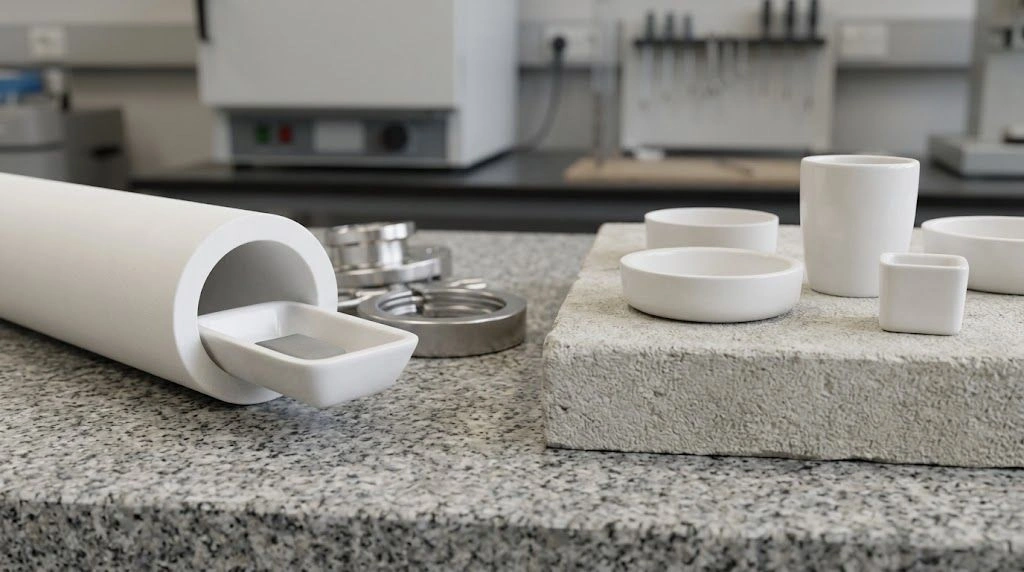
Actual boats, tubes, and crucibles make load envelope and clearance checks visible.
What Assumptions About Atmosphere and Temperature Cause Wrong Selections?
“Tube furnace” does not automatically mean gas-tight. A tube with open ends, incompatible end hardware, or a poor seal does not satisfy a controlled-atmosphere requirement. The complete assembly needs a suitable rating and verification for its intended gas, pressure, and temperature conditions. This is particularly important when replacing only the ceramic tube: its end finish and dimensions must match existing interfaces without assuming the old sealing result will carry over.
“Muffle furnace” does not automatically mean every model can operate only in ambient air. Some specialized chamber systems can be configured for particular atmospheres. Conversely, a vent port on a standard model is not proof of a controlled or sealed atmosphere. Specify the exact process condition and request model documentation rather than relying on either name.
Setpoint, maximum rating, and sample temperature
A controller measures temperature at its sensor, not necessarily at every sample. Loads, covered crucibles, and positions near a working-zone edge can change exposure. A maximum rating may depend on duration or atmosphere. The cited MTI model publishes separate limits for short, continuous, and vacuum operation; they apply only to that configuration.
Uniformity claims may describe a specified region and survey condition. Shelf position, loading, and a boat extending beyond the verified zone can alter sample exposure. Check the rating basis and validate critical loaded processes.
Material and interface assumptions
An alumina work tube is not automatically suitable for every sample, gas, thermal cycle, or seal geometry. Sample vapors, condensates, powders, and contact materials may affect compatibility or contamination risk. Mechanical constraints matter too: end clamps, supports, and thermal expansion can load a brittle tube. For a chamber arrangement, the crucible, tray, or shelf material likewise needs a compatibility review. Material selection follows the actual process boundary.
When Does Each Setup Fit Better?
Choose the arrangement that can demonstrate the required sample environment while accommodating the real load. A compatible tube and end assembly are a strong starting point when a defined sample path or specified gas flow is central to the process. An accessible chamber is a strong starting point when multiple containers, broad loading access, or a load that cannot fit a practical tube bore governs the work. In either case, a failed atmosphere, geometry, or temperature-position requirement overrides the apparent convenience of the layout.
Tube furnace versus muffle furnace selection matrix
| Criterion | Tube-furnace direction | Muffle-furnace direction | Required verification |
|---|---|---|---|
| Sample atmosphere | Consider a compatible tube and end assembly for the specified gas path. | Consider a chamber only when its exact configuration demonstrates the required environment. | Gas or atmosphere specification, flow or pressure conditions, and complete equipment configuration. |
| Load geometry | Check usable ID, boat or holder, clearances, and tube support. | Check usable chamber space, shelf, container footprint, and loading access. | Sample and fixture drawings against equipment dimensions. |
| Heated region | Place the load in the verified tube working zone. | Confirm the relevant chamber positions under the planned load. | Model-specific zone or temperature-survey information. |
| Sample containment | Check boat, holder, and any protective container inside the tube. | Check crucible, tray, lid, and support compatibility. | Sample chemistry, contact surfaces, capacity, and containment needs. |
| Ceramic component | Specify tube OD, ID, length, ends, supports, and seal interface. | Specify vessel shape, footprint, volume, lid, and support. | Drawing, cycle, atmosphere, sample conditions, and inspection requirements. |
The matrix gives conditional directions. It makes no universal claim that one architecture reaches a higher temperature, heats faster, uses less energy, or has a longer service life. NIST’s record for a specific chamber furnace likewise presents chamber size and temperature capability as properties of that equipment, which is the right level at which to compare ratings.
Exceptions and process transfer
The same material may use either furnace if its atmosphere, container, temperature, and loading requirements are met. On transfer, compare sample position, container, gas path, cycle, and result checks; similar controller settings do not establish equivalent exposure.
What Should a Ceramic-Component RFQ Include?
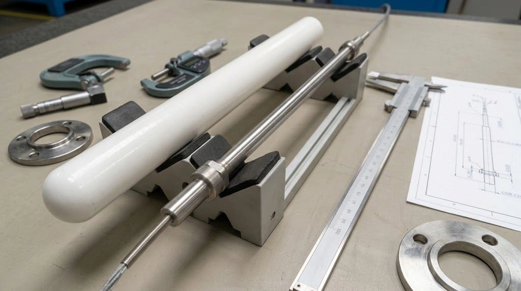
Specify the ceramic part after selecting the configuration. For a replacement work tube, send the furnace model, tube drawing or measured sample, and installation layout. Mark heated-zone location, support points, end seals, and fit-critical dimensions.
Copyable alumina work-tube RFQ checklist
- Furnace make, model, orientation, and assembly drawing or photos of the interfaces.
- Existing tube material or proposed grade, if known; sample and process chemistry.
- Tube OD, ID, wall thickness, total length, and whether the ends are open or closed.
- End geometry, grooves, steps, flange features, chamfers, and sealing surfaces.
- Fit-critical dimensions, tolerances, straightness, end-face condition, and inspection method.
- Heated-zone start and end locations measured from a stated tube datum.
- Support positions, unsupported span, boat or holder dimensions, and loading method.
- Peak and continuous temperature, hold duration, heating and cooling cycle, and number of cycles.
- Atmosphere, gas composition, flow or pressure requirement, and compatible end assembly.
- Prototype or replacement quantity, target inspection records, and packaging needs.
OD and length alone leave the mating interface unresolved. For a damaged tube, use an undamaged reference region and mating-hardware drawing. Agree on end-feature inspection, finished surfaces, and any prototype fit check. The equipment owner must verify the assembled furnace, gas, and seal arrangement.
Chamber-furnace container details
If the chosen arrangement is a chamber furnace, the relevant ceramic RFQ may be for a crucible, tray, boat, or support rather than a work tube. Supply sample chemistry and quantity, container capacity and outer footprint, lid or vent requirement, chamber and shelf clearance, contact surfaces, temperature cycle, and loading pattern. State whether the container’s function is containment, separation, contamination control, or easy handling. A tube-specific quote should not be forced into a chamber process.
Frequently asked questions
Is a tube furnace always better for a controlled atmosphere?
No universal ranking follows from the name. A tube arrangement can provide a defined gas path when the tube, end hardware, and complete system are compatible and verified. A specialized chamber may also meet a defined atmosphere requirement.
Can the same sample be heated in either furnace?
Sometimes. Check the atmosphere, containment, load size, working zone, and temperature at the actual sample position. Revalidate the process when changing equipment or sample placement.
Is a muffle furnace always hotter than a tube furnace?
No. Compare the selected models’ allowable temperatures under the intended duration and atmosphere, then check the working region relevant to the load.
What dimensions matter for a replacement alumina work tube?
Provide OD, ID, wall, total length, end features, seal interfaces, support positions, and the heated-zone position. Mark fit-critical tolerances and inspection requirements on a drawing.
The decision is complete when the required sample environment is matched to a documented furnace configuration and the exposed ceramic components are specified at their actual interfaces.
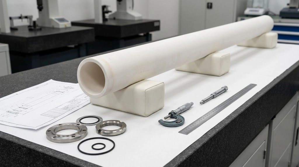
A physical work tube and mating hardware show the dimensions and interfaces needed for an RFQ.